High Voltage Power Amplifier Circuit Diagram

Electronic Devices Bjt Amplifiers Part 3
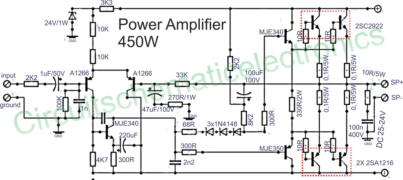
450w Amplifier Circuit Electronics Circuit
Audio Amplifiers

3000 V µs High Voltage Power Amplifier Apex Precision Product Pdf Catalogs Technical Documentation Brochure
Amplifier Circuit Diagram Power Amplifier Voltage Amplifier

3000w Stereo Power Amplifier Circuit Electronic Circuit Hifi Amplifier Audio Amplifier Electronics Circuit
Circuit diagram of a three stage practical audio power amplifier is shown in the figure below Small signal transistor Q1 and its associated components form the voltage amplification stage R1 and R2 are biasing resistors of Q1 C4 is the input coupling capacitor which blocks DC components from the input signal.
High voltage power amplifier circuit diagram. HIGH VOLTAGE 0400V 22MA600MA REGULATED POWER SUPPLY TC85 Schematic Circuit Diagram TD560 4X50 WATT BRIDGE AUTO AMPLIFIER SCHEMATIC CIRCUIT DIAGRAM QUALITY DISTORTION OVERDRIVE EFFECT CIRCUITRY NE5532 SCHEMATIC CIRCUIT DIAGRAM. The amplifier bias circuit applies adjustable regulated bias to the 6146B control grid The use of regulated bias results in improved linearity, important when the amplifier is used for SSB service To avoid the expense of a separate power transformer, a filament transformer is run in reverse to step some of the filament voltage from the main. This circuit is of an 2x 2,500W RMS stereo amplifier, superlight and without switchingmode power supply The circuit just shows a channel, and the power supply that it assists to the two channels The audio circuit should be duplicated, but the power supply assists to the two channels without problems A special care should beRead More.
Intermediate Frequency Amplifier These amplifiers operate and the bandwidth of the amplifier depends on the type of equipment that used The AM radio receivers and the IF amplifiers operate at around 470 kHz and their bandwidth is normally 10 kHz ie 465 kHz to 475 kHz, home TV commonly uses 6 MHz bandwidth for the IF Signal at around 30 to 40 MHz and in radar a bandwidth of 10 MHz may be. Circuit diagram of a three stage practical audio power amplifier is shown in the figure below Small signal transistor Q1 and its associated components form the voltage amplification stage R1 and R2 are biasing resistors of Q1 C4 is the input coupling capacitor which blocks DC components from the input signal. Mono high power amplifier circuit is actually powerful, output about 1400 W, but if this high power amplifier circuit is doubled and you want to create stereo power amplifier, this high power amplifier circuit the necessary components and PCB requires twofold So if the stereo high power amplifier 2 X 1400W Power Output ( 2800W ) Power Amplifier Circuit Diagram is still less by looking at.
Here is the 100W RMS audio amplifier schematic diagram This circuit is quite simple but will give you high quality audio output Take a note that above diagram designed for single input and single output (mono system) For stereo system, you need to build two similar circuits The input stage. Circuit Diagram Working Explanation The TD003 amplifier IC delivers a 7 Watt output power using a 12V, 500mA power supply with a 4Ω speaker TD003A is a 5pin audio amplifier IC The pins 5 & 3 power the Amplifier IC, and the audio signal to be amplified is given in through pin 1 which is the noninverting input. HIGH VOLTAGE 0400V 22MA600MA REGULATED POWER SUPPLY TC85 Schematic Circuit Diagram TD560 4X50 WATT BRIDGE AUTO AMPLIFIER SCHEMATIC CIRCUIT DIAGRAM QUALITY DISTORTION OVERDRIVE EFFECT CIRCUITRY NE5532 SCHEMATIC CIRCUIT DIAGRAM.
Circuit Diagram Working Explanation The TD003 amplifier IC delivers a 7 Watt output power using a 12V, 500mA power supply with a 4Ω speaker TD003A is a 5pin audio amplifier IC The pins 5 & 3 power the Amplifier IC, and the audio signal to be amplified is given in through pin 1 which is the noninverting input. The below circuit diagram shows the working of the common emitter amplifier circuit and it consists of voltage divider biasing, used to supply the base bias voltage as per the necessity The voltage divider biasing has a potential divider with two resistors are connected in a way that the midpoint is used for supplying base bias voltage. A power amplifier circuit is the one with minimum output impedance, used to drive loads like a speaker, which require high power at low impedance Here we designed a power amplifier circuit using push pull class AB configuration to derive a power of 150W to drive a load of 8 Ohms (speaker).
Description The LM358 consists of two independent, high gain, internally frequency compensated operational amplifiers which were designed specifically to operate from single power supply over a wide range of voltages Operation from split power supplies is also possible and the low power supply current drain is independent of the magnitude of the power supply voltage. However, in cascade amplifier meant for providing high gain, only CE amplifier stage are connected in cascade CB and CC configurations can not be used for this purpose Figure 2 gives the circuit of a two stage CE audio amplifier The circuit gives the typical biasing arrangement and use of coupling capacitors C b1 and C b2 Typical values of. 500W RMS Power Amplifier PCB Design and Layout This is the PCB design and component placement, you should mount the MOSFET on the heatsink to prevent overheating and maintain the performance of power amplifier This circuit designed by Dr Borivoje Jagodic >> original page for the reference.
A reference voltage from 0 to 1 volt is applied to the other opamp input to set the threshold current and when the DUT current exceeds this current the 2N4401 turns on and steals current from the 002 uF capacitor in the flasher circuit, limiting the output voltage. HIGH VOLTAGE 0400V 22MA600MA REGULATED POWER SUPPLY TC85 Schematic Circuit Diagram TD560 4X50 WATT BRIDGE AUTO AMPLIFIER SCHEMATIC CIRCUIT DIAGRAM QUALITY DISTORTION OVERDRIVE EFFECT CIRCUITRY NE5532 SCHEMATIC CIRCUIT DIAGRAM. This circuit is of an 2x 2,500W RMS stereo amplifier, superlight and without switchingmode power supply The circuit just shows a channel, and the power supply that it assists to the two channels The audio circuit should be duplicated, but the power supply assists to the two channels without problems.
180V, wide bandwidth, highslew rate, power amplifier It features input overvoltage protection, output current limiting, thermal protection, a status flag, and enabledisable capability Online datasheet. Equivalent Circuit For Amplifiers Most high voltage power supplies, to allow high voltage current measurements (plate current) without having dangerously high voltages on the meter, and to also allow grid current measurements in grounded grid amplifiers, are constructed with the negative power supply lead floating from chassis ground. This is a Protection circuit from high voltage to any device by the automatic cutoff using popular ic 741 Note Connect the load with NC pin of the relay When the input voltage at Non inverting pin of opamp 741 is cross over the set reference voltage.
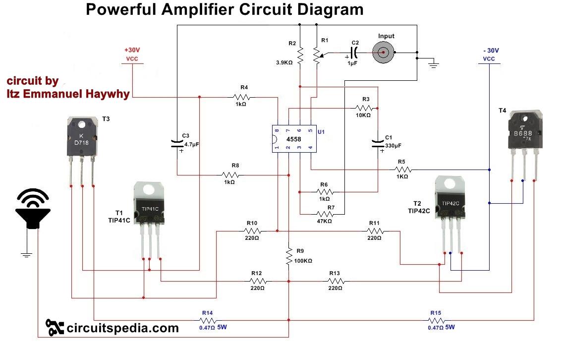
Circuit Description This is a 100 watt basic power amp that was designed to be (relatively) easy to build at a reasonable cost It has better performance (read musical quality) than the standard STK module amps that are used in practically every mass market stereo receiver manufactured today. The high voltage secondary feeds a conventional full wave bridge rectifier to convert the AC to unfiltered DC, which is then fed to the plate power supply filter Since the the PIV rating of one diode is not enough, two must be used in series, so the four diodes D1 through D4 are actually two 1N4007 diodes in series. Circuit 1 4558 ic Audio Power Amplifier Circuit Diagram This is circuit diagram of powerful audio amplifier This circuit is given by Emmanuel In this circuit one ic 4558 and 4 Power transistors are used with some discrete components Use vto 60v for operating this circuit This is a single channel audio amplifier circuit.
Here you will find how an ordinary LM317 circuit could be converted into a high current amp variable power supply circuit using just a few 2n3055 power transistors in conjunction with a standard LM317 voltage regulator circuit stage. Multiple voltage power supply circuit diagram schematic to get output voltage of 12V, 9V, 6V, 5V and 33V LM317 based adjustable voltage regulator project Valve Amplifier Reference Book Circuit Diagram Vacuum Tube Audio Circuits Horn. A voltage amplifier circuit is a circuit that amplifies the input voltage to a higher voltage So, for example, if we input 1V into the circuit, we can get 10V as output if we set the circuit for a gain of 10 Voltage amplifiers, many times, are built with op amp circuits However, with a transistor and the correct biasing, we can produce the.
And you need to make sure that the capacitors that you are using for filtering are rated for high voltage, at least 100VAC (more doesn't hurt) The rest of the capacitors in the design also need to have an appropiate voltage rating I designed this amplifier for an output power of about W You should use a bipolar power supply with ±30V. HIGH VOLTAGE APPLICATIONS The following applications make use of the high voltage capabilities of the LM143 As with most general purpose op amps, the power supplies should be adequately bypassed to ground with 01 µF capacitors 130 Vpp Drive to a Floating Load A circuit diagram using two LM143’s to drive up to 130V peaktopeak is given. The simple mosfet amplifier circuit diagram is super simple to build and yet will provide you with a crystal clear 100 watts of raw music power that all the listeners will cherish for a long time The idea was developed a long time ago by the Hitachi researchers and still it remains one of the favorite designs of all time considering the.
High voltage, highside floating current sensing circuit using current output current sense amplifier Lowdrift, lowside, bidirectional current sensing circuit with integrated precision gain resistors. Mono high power amplifier circuit is actually powerful, output about 1400 W, but if this high power amplifier circuit is doubled and you want to create stereo power amplifier, this high power amplifier circuit the necessary components and PCB requires twofold So if the stereo high power amplifier 2 X 1400W Power Output ( 2800W ) Power Amplifier Circuit Diagram is still less by looking at. A voltage amplifier circuit is a circuit that amplifies the input voltage to a higher voltage So, for example, if we input 1V into the circuit, we can get 10V as output if we set the circuit for a gain of 10 Voltage amplifiers, many times, are built with op amp circuits However, with a transistor and the correct biasing, we can produce the.
A reference voltage from 0 to 1 volt is applied to the other opamp input to set the threshold current and when the DUT current exceeds this current the 2N4401 turns on and steals current from the 002 uF capacitor in the flasher circuit, limiting the output voltage. 12V 50 watt audio amplifier LM3876 is a high performance audio power amplifier IC from National Semiconductors The LM3876 can deliver 50watts of output power into an 8 Read More. Circuit Diagram Working Explanation The TD003 amplifier IC delivers a 7 Watt output power using a 12V, 500mA power supply with a 4Ω speaker TD003A is a 5pin audio amplifier IC The pins 5 & 3 power the Amplifier IC, and the audio signal to be amplified is given in through pin 1 which is the noninverting input.
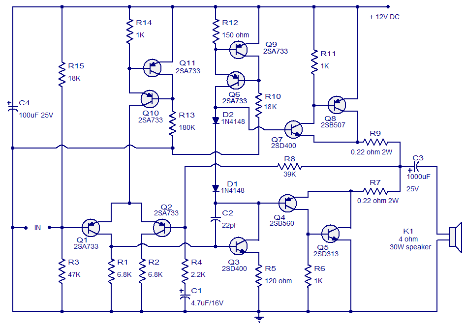
Using evolved techniques, completed amplifier STK465, can minimise the deformities even in highest levels of force Other characteristically that determines the completed circuit they are the wide area and the high aid Schematic STK465 is drawn to be constant, when it functions in conjunction closed bronchi with big gain. 1600W High Power Amplifier Circuit Diagram In the buffer circuit coupled with opamp ic 4558, supplied 15VDC voltage, circuit power supply you can see in the picture is flavored transistor D313 and B507 Driver circuit using transistor MJ40 MJ50 For use transformer, it's using one transformer by one circuit mono. The driver stage is employed in order to get a high impedance input for the power amplifier In this article we work with a power transistor TIP41 in class A function The emitter resistor, R8 is determined through the values of emitter voltage, Ve (1/2Vcc 07) and emitter current, Ie (equal to collector current, ie 05A) and it is.
A power amplifier circuit is capable of providing highfrequency output signals over a wide voltage range At least two transistors are coupled in series to a load terminal and the transistors are energized by respective voltage sources having different magnitudes. Circuit Diagram Working Explanation The TD003 amplifier IC delivers a 7 Watt output power using a 12V, 500mA power supply with a 4Ω speaker TD003A is a 5pin audio amplifier IC The pins 5 & 3 power the Amplifier IC, and the audio signal to be amplified is given in through pin 1 which is the noninverting input. In the amplifier’s amplification stage, we used high voltage transistor MPS3 It is a high voltage NPN transistor which acts as an Amplifier The pin out of the MPS3 NPN transistor is Circuit Diagram for 100 Watt Power Amplifier Circuit using MOSFET.
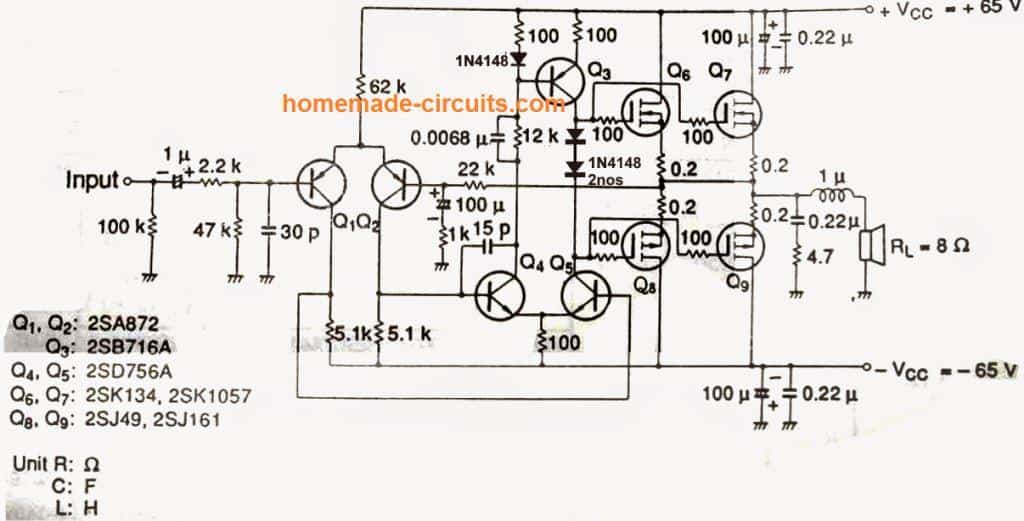
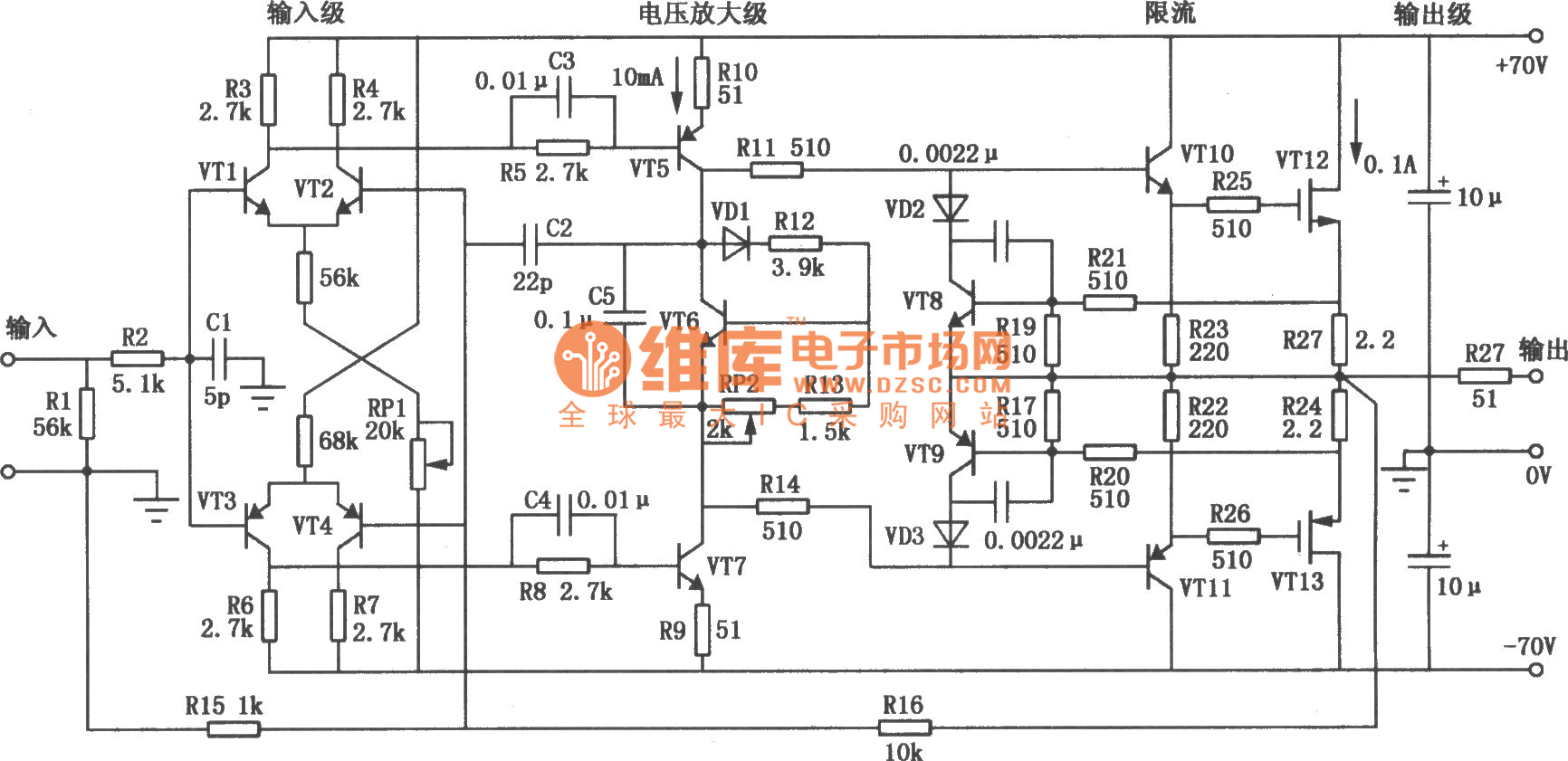
Here is the variable high voltage dc power supply circuit, which we can customize the output voltage from 0 to 311Vdc, and it is protected the current over the limit that we define at about 100 mA You may like these LM338 5A Variable regulator Better life with high current in same voltage 125V to 30V In the circuit, you can see the T1 is a mains transformer with a ratio of 11, for. HIGH VOLTAGE APPLICATIONS The following applications make use of the high voltage capabilities of the LM143 As with most general purpose op amps, the power supplies should be adequately bypassed to ground with 01 µF capacitors 130 Vpp Drive to a Floating Load A circuit diagram using two LM143’s to drive up to 130V peaktopeak is given. This high power audio amplifier circuit consists of a differential amplifier as first stage amplifier Potentiometer VR1 is used to adjust the offset voltage of the amplifier before entering the next level Transistors Q7 and Q8 on this amplifier circuit serves as protection against short circuit, which flows out through the final stage transistor will be limited to about 12 Ampere The.
Circuit Description This is a 100 watt basic power amp that was designed to be (relatively) easy to build at a reasonable cost It has better performance (read musical quality) than the standard STK module amps that are used in practically every mass market stereo receiver manufactured today.
60 Watt Audio Power Amplifier Circuit Diagram Circuit Diagram

High Power Amplifier Circuit Diagram Circuit Diagram Images Circuit Diagram Power Amplifiers Audio Amplifier
Q Tbn And9gcsfv Kzde 2rhnv3rxz S5jnneee3u2f4w93odtregqdmm Onih Usqp Cau

Low Voltage Audio Amplifier
Balancer More Class G
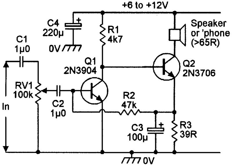
Small Audio Power Amplifier Using 3 Transistors Deeptronic

High Voltage Power Supply Based Pwm Ic Tl494 Power Supply Circuits

Hybrid Amplifier By Andrea Ciuffoli
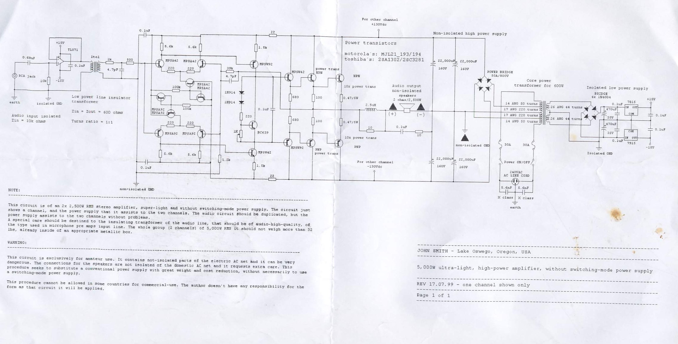
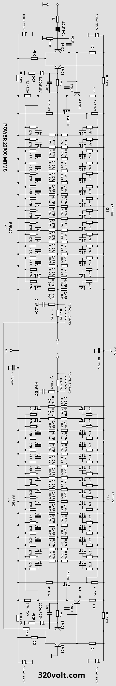
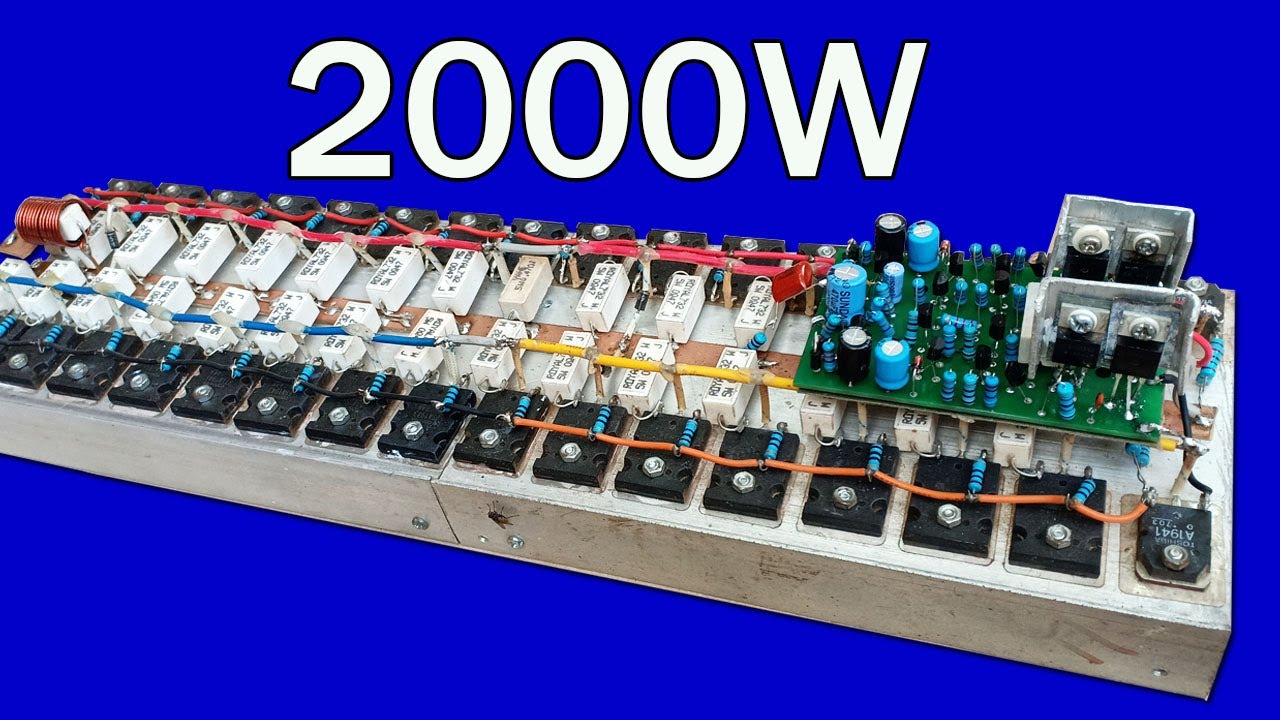
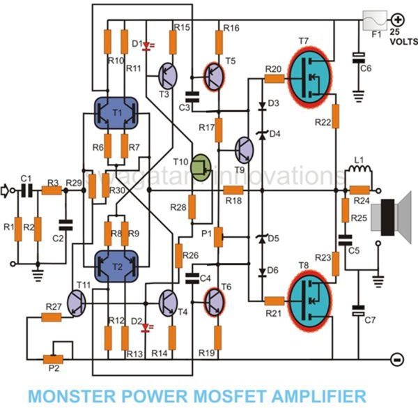
5000w Ultra Light High Power Amplifier Electronics Lab Com

Sensors Free Full Text A High Voltage And Low Noise Power Amplifier For Driving Piezoelectric Stack Actuators Html

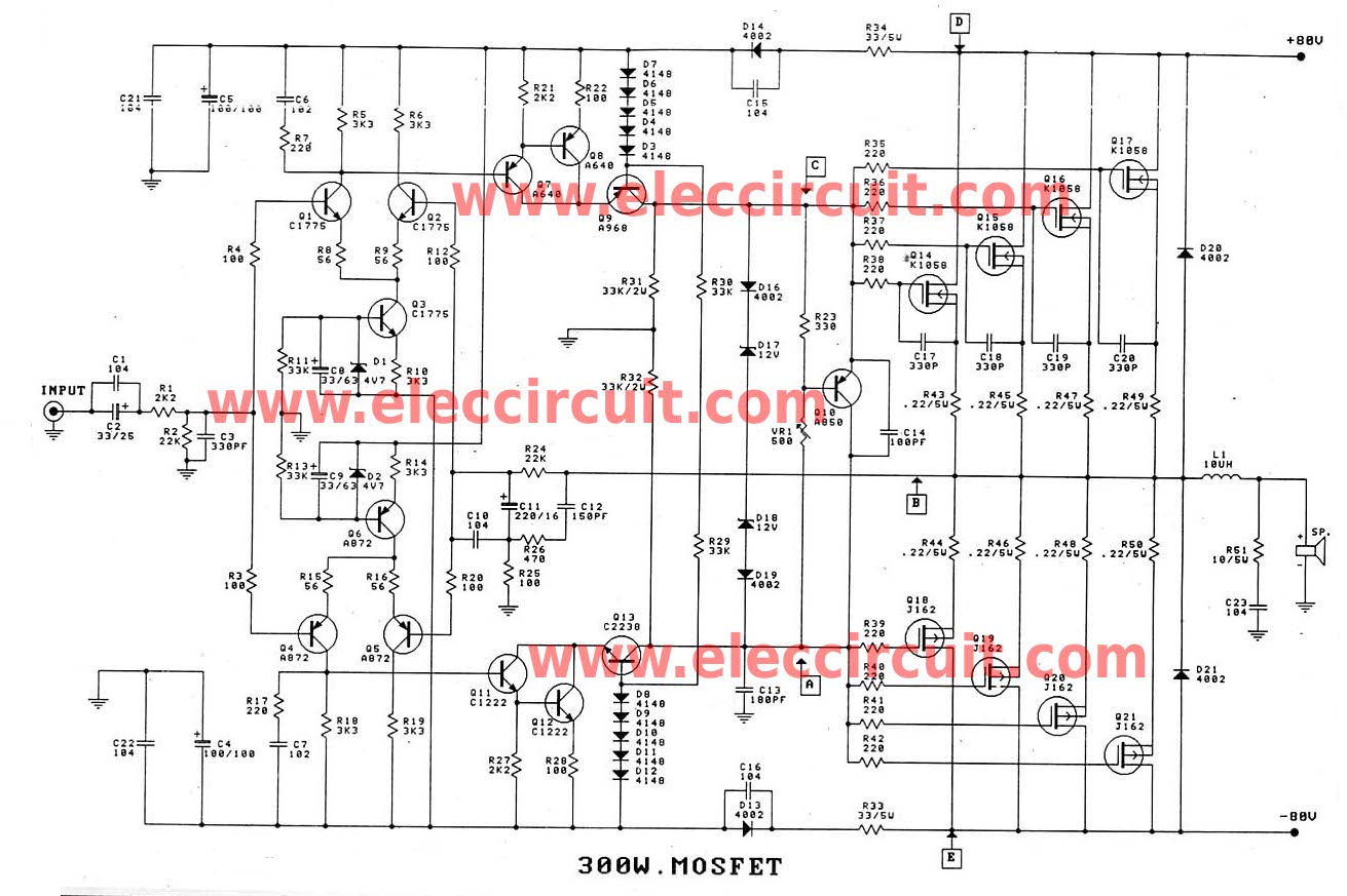
300 Watt Mosfet Real Hi Fi Power Amplifier Eeweb
18w Audio Amplifier Circuit Diagrams Schematics Electronic Projects
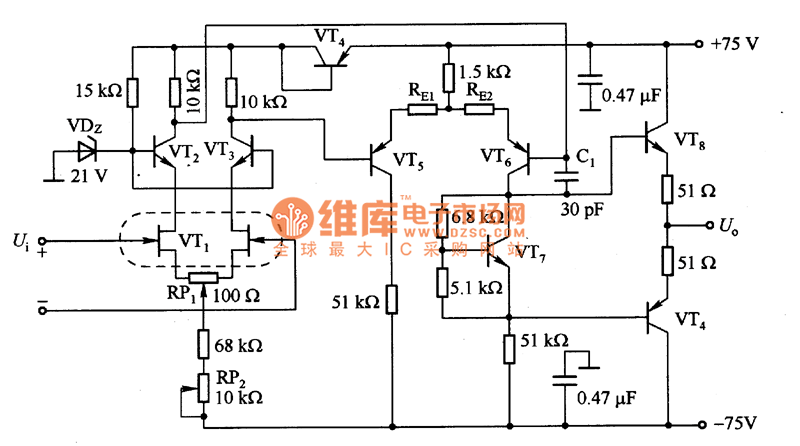
The High Voltage Input Fet Power Amplifier Circuit Diagram Amplifier Circuits Audio Amplifier Circuit Circuit Diagram Seekic Com

Amplifier Circuit Diagram Power Amplifier Voltage Amplifier
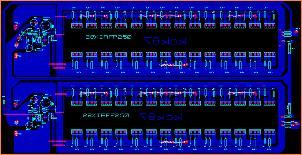
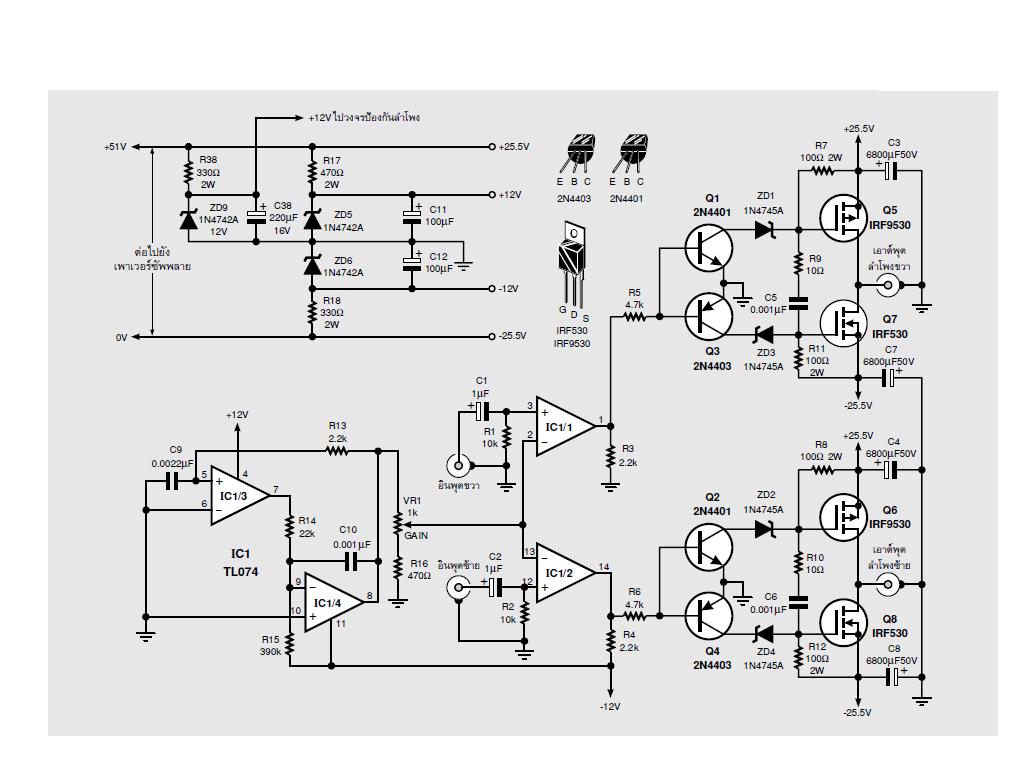
Mosfet Power Amplifier 50w Irfp250 Amplifier Circuit Design

Amplifier Wikipedia

High Voltage 3 Watt Audio Power Amplifier Circuits Projects

High Voltage Converter Circuit

12 Watt Audio Amplifier Circuit Using Tda2616 Power Amplifier
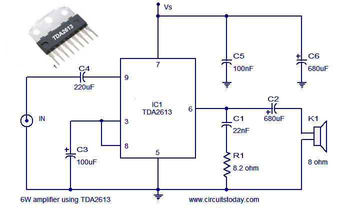
Audio Power Amplifier Circuit Using Hi Fi Audio Amplifier Ic Tda2613
300 10w Mosfet Amplifier For Professionals Projects Circuits

Amplifier Circuit Diagram Power Amplifier Voltage Amplifier

70 Watt High Efficiency Power Amplifier Circuit Using Ic Tda1562
How To Make Audio Power Amplifier Circuit Electronic Projects Design Ideas Electronics Lab Com Community
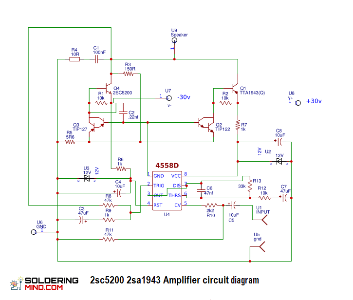
2sc50 2sa1943 Amplifier Circuit Diagram Soldering Mind
High Power 20w Amplifier Circuit Electronics Projects Circuits
Hv Power Supply
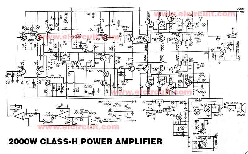
Powerful 00w Power Amplifier Class H Electronic Circuit
50 Watt Power Amplifier Circuit Diagram Using Mosfets
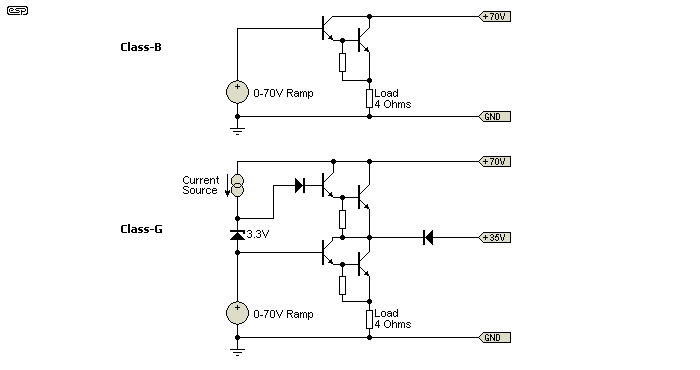
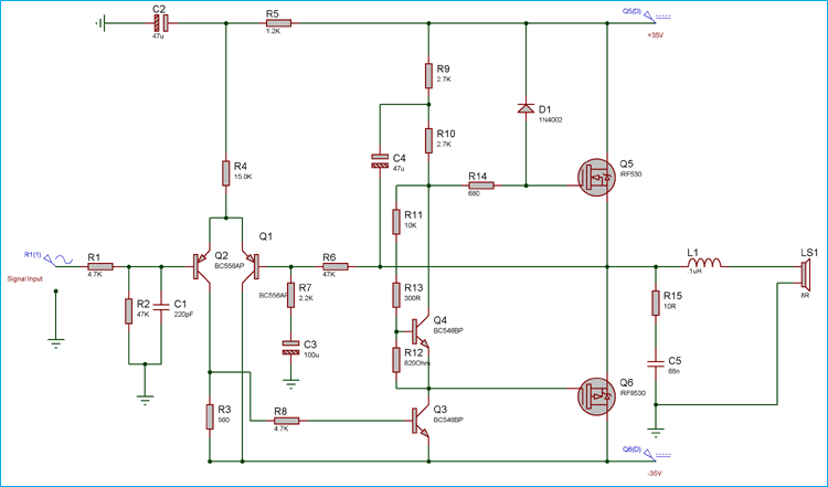
Class G Amplifiers

How To Build Motorola Hi Fi Power Amplifier Circuit Diagram

50 Watt High Power Mosfet Amplifier Diyaudio

Stk4231 Ii 100w 100w Stereo Audio Amplifier Circuit Diagram 100 Watts Amplifier
Index 1760 Circuit Diagram Seekic Com

Class A Amplifier Is A Class A Transistor Amplifier

High Voltage Amplifier Uses Simplified Circuit Edn
Audio Power Amplifier Circuit Diagram
Power Amplifier Basics Types Classes And Its Applications
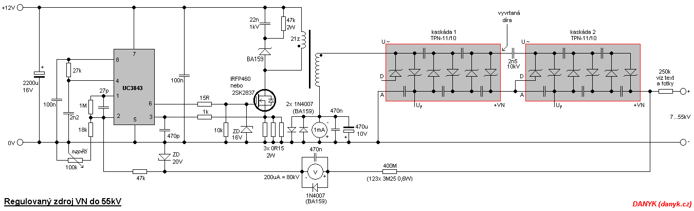
Adjustable Stabilized Switching High Voltage Supply 7 55kv
High Voltage Circuit Page 2 Power Supply Circuits Next Gr
High Power 20w Amplifier Circuit Electronics Projects Circuits
An Interesting Class D Amplifier Design Regulated 2v 2x60w Electronics Projects Circuits

Using Low Voltage Drivers To Boost Rf Power Amplifier Efficiency Industry Articles

High Voltage Amplifier Uses Simplified Circuit Edn

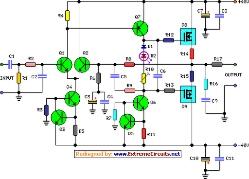
Range Extender Amplifier Schematics Based On Apex Mod Pa Download Scientific Diagram
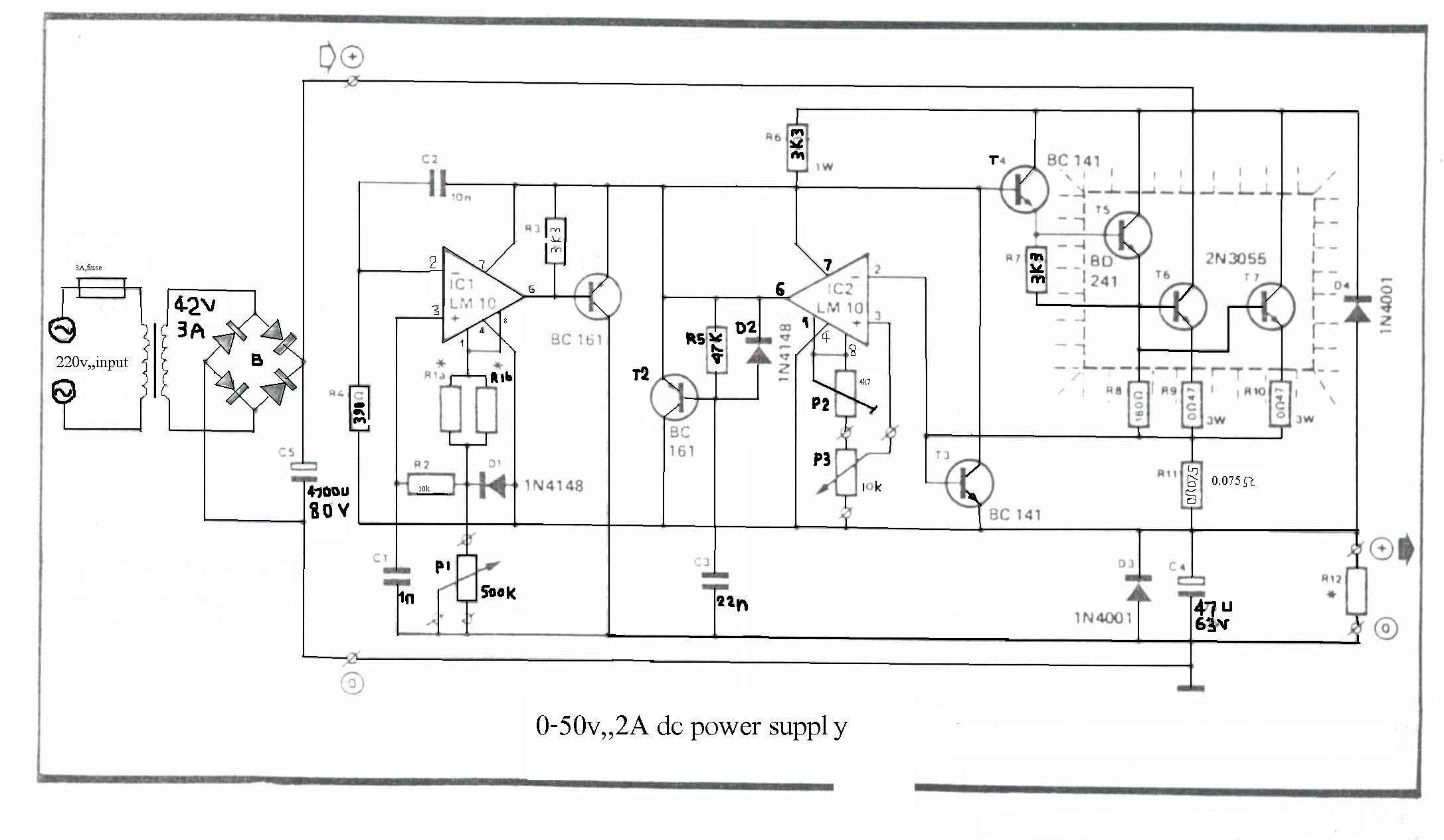
How To Build 0 50v 2a Bench Power Supply Circuit Diagram
How Amps Work
3
Q Tbn And9gcqwn1 Lk4cvxhzme2v8p 5tcuzgzrsuuct0pmrraemcov E E G Usqp Cau
Bipolar Transistor Cookbook Part 7 Nuts Volts Magazine
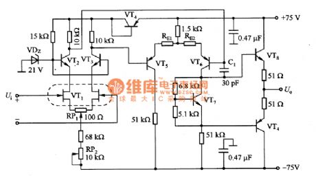
Schematic Diagram Of High Voltage Dc Amplifier Download Scientific Diagram

High Voltage Power Supply With Dual Output Power Supply In Amplifier
Diy 100 Watt Mosfet Amplifier Circuit Homemade Circuit Projects

High Voltage Regulator Schematic Circuit Diagram
How To Make 00w Amplifiers Circuit Diagram At Home Youtube
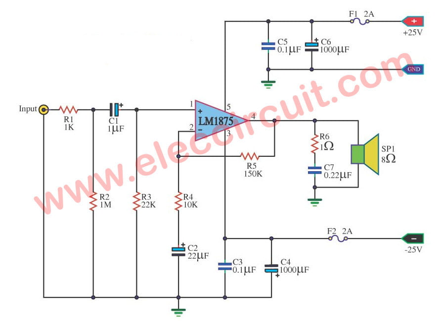
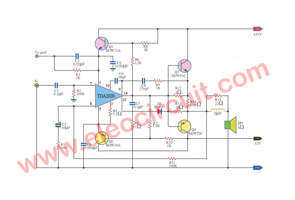
Lm1875 Datasheet 25w Hifi Audio Amplifier Circuit Eleccircuit Com
150 Watt Power Amplifier Circuit Diagram Working And Applications
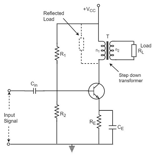
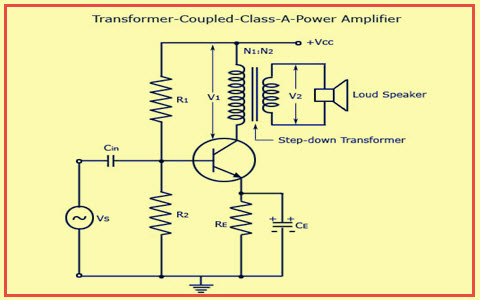
Transformer Coupled Class A Power Amplifier Tutorialspoint

Pin On Hubby Project
A Low Drive Grounded Grid 3cx800a7 Amplifier
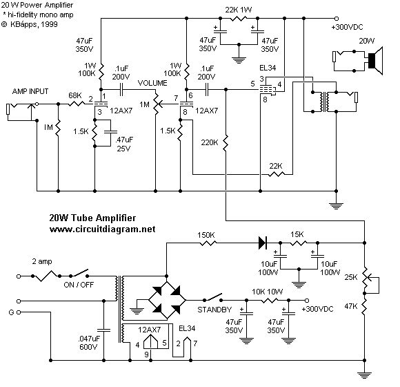
w Power Tube Amplifier With El34 Electronic Schematic Diagram

Figure 12 From A High Voltage Class D Power Amplifier With Switching Frequency Regulation For Improved High Efficiency Output Power Range Semantic Scholar
1000 Watt To 00 Watt Power Amplifier Circuit Homemade Circuit Projects
High Voltage High Exchange Rate Power Amplifier Circuit Diagram Amplifier Circuit Circuit Diagram Seekic Com
Class A Amplifier Circuit Operation And Applications
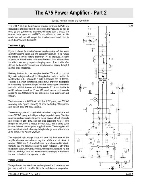
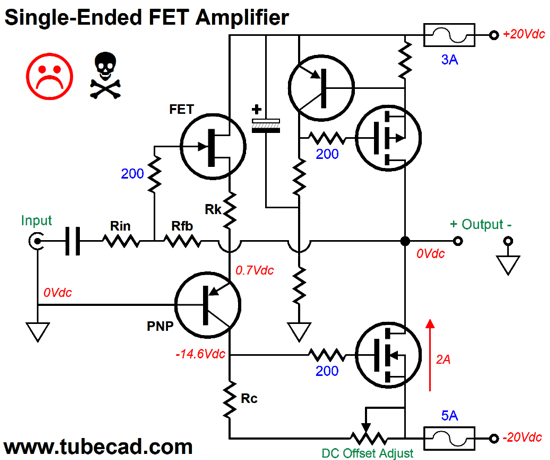
The 5 Power Amplifier Part 2 First Watt

Schematic Diagram Of The High Voltage Amplifier Circuit Each Printed Download Scientific Diagram
High And Low Voltage Cut Off With Time Delay Circuit Diagrams Schematics Electronic Projects
0w Audio Amplifier Circuit Diagrams Schematics Electronic Projects

Mini Amplifier With High Power Output Electronic Circuit

Pin On De Vizitat
1000 Watt To 00 Watt Power Amplifier Circuit Homemade Circuit Projects
100watt Mosfet Power Amplifier Circuit Working And Applications
40 Watt Audio Amplifier Circuit Diagram Using Tda40 And Transistor Pair
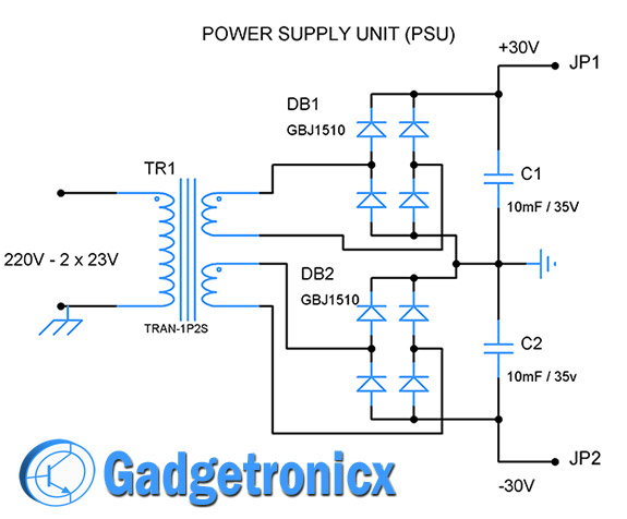
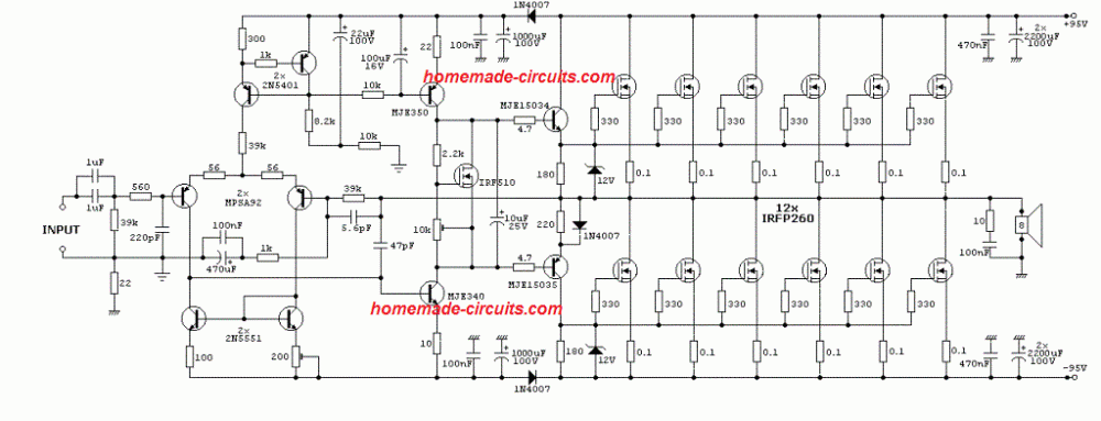
50w Diy Hi Fi Audio Amplifier With Protection Circuitry Gadgetronicx

High Performance Power Amplifier 400 Watt Power Amplifiers Audio Amplifier Circuit Diagram
500w Audio Power Amplifier Circuit Diagram With Transistor Electronic Circuits Diagram

100 Watt Power Amplifier Circuit Diagram Using Mosfet

Circuit Diagram Of 6000w High Power Amplifier Page 1 Line 17qq Com
150 Watt Power Amplifier Circuit Working And Applications

1kw Rms Mosfet Amplifier 1kw Rms Mosfet Amplifier Shematic Schematic Circuits Elektropage Com

0w Hybrid Audio Amplifier Circuit
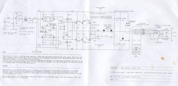
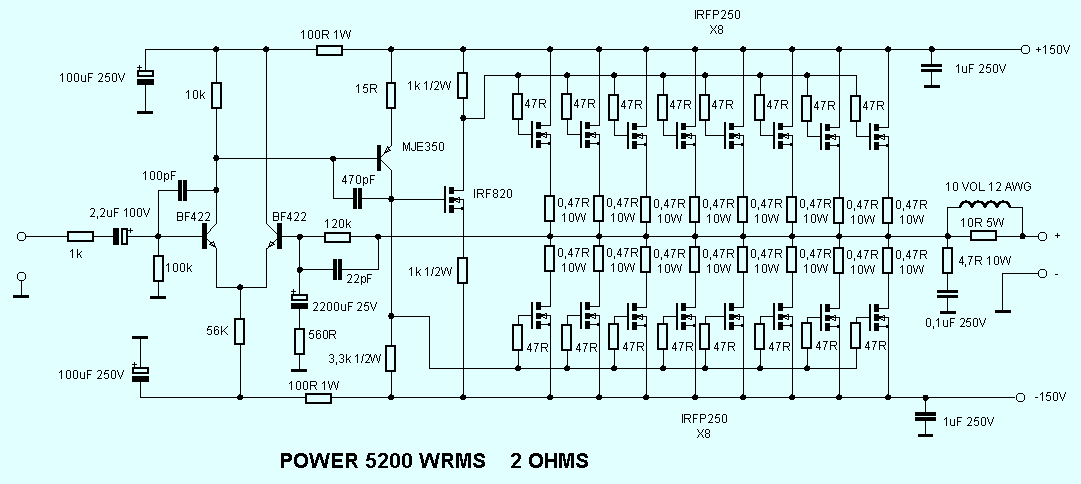
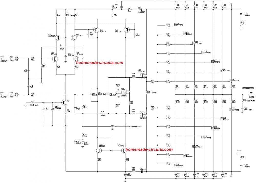
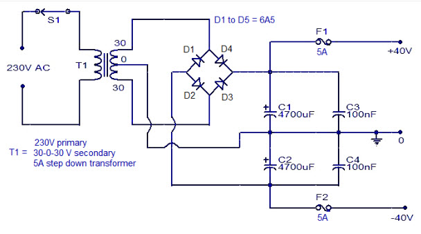
How To Build 5 000w Ultra Light High Power Amplifier Without Switching Mode Power Supply Circuit Diagram
Class Ab Amplifier Circuit Operating From 12 Volts 10w Fully Transistorized

Schematic Diagram Of The High Voltage Amplifier Circuit Each Printed Download Scientific Diagram
60 Watt Audio Power Amplifier Circuit Diagram Circuit Diagram

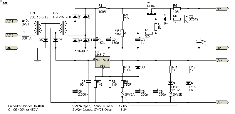
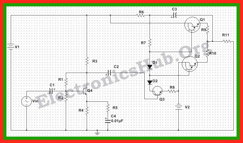
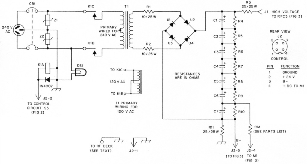
The 8v 6146b Amplifier Power Supply Schematic Diagrams And Circuit Descriptions

A Paul Kemble Web Page Mission Cyrus 1 Integrated Amplifier
Tda Ocl Hi Fi Power Amplifier w To 80w Eleccircuit Com

Figure 1 From A High Voltage Class D Power Amplifier With Switching Frequency Regulation For Improved High Efficiency Output Power Range Semantic Scholar
Transistor Amplifier Circuit With Diagram For 12 Watts

2800w High Power Amplifier Circuit Updated Electronic Circuit

12 Volt 30 Amp Power Supply

Pin On Hubby Project
How To Build A 100 Watt Mosfet Amplifier Circuit Simple Design Explored Bright Hub Engineering

100 Watt High Quality Power Amplifier Amplifier Circuit Design

Class A Amplifier Is A Class A Transistor Amplifier
Q Tbn And9gcrh1mswkjizmh4hloqr8iy Brq8ttelgweqmvv3hdp31rg Awyw Usqp Cau


