High Voltage Audio Amplifier Circuit Diagram
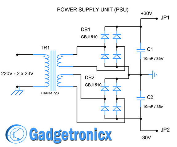
50w Diy Hi Fi Audio Amplifier With Protection Circuitry Gadgetronicx
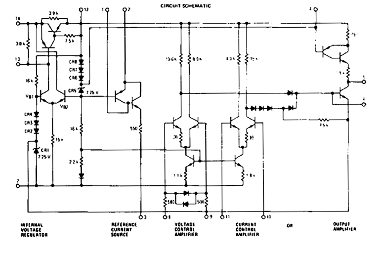
T Reg A High Voltage Regulator For Tube Amps Audioxpress
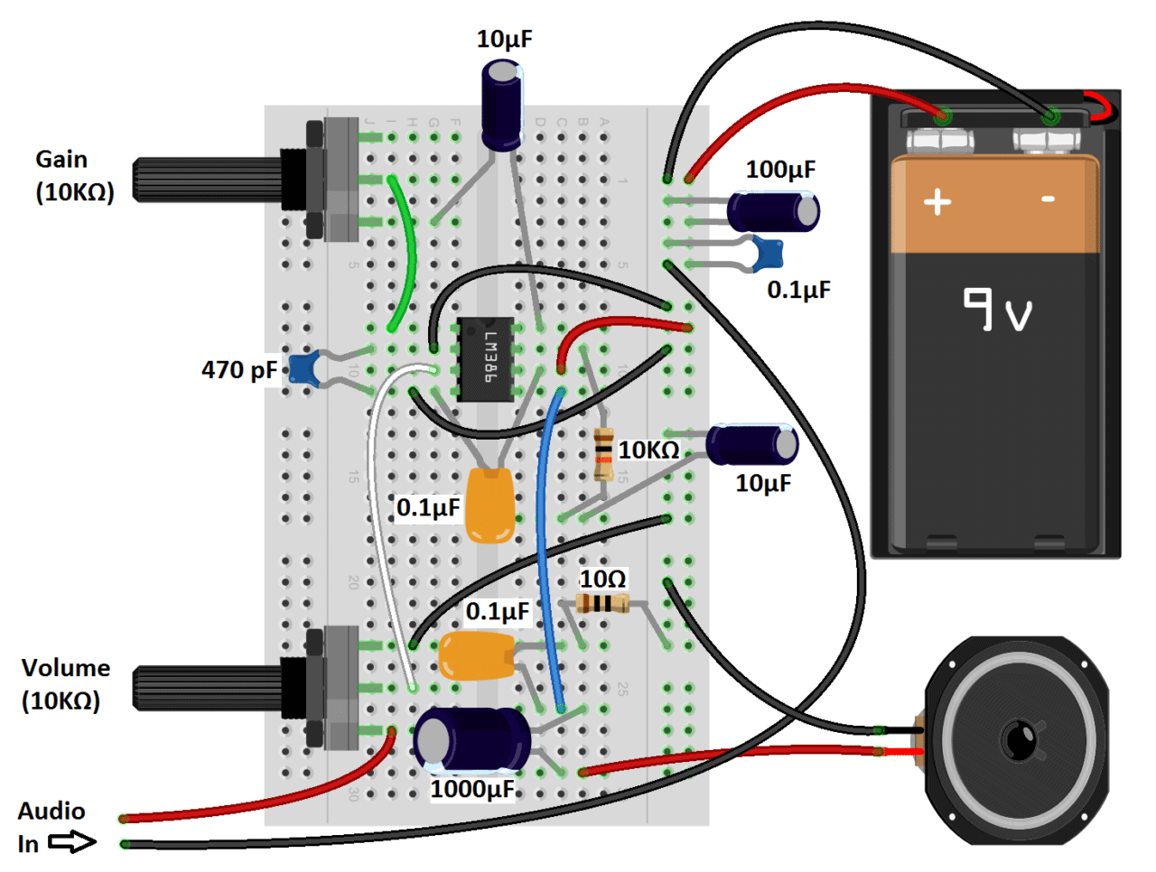
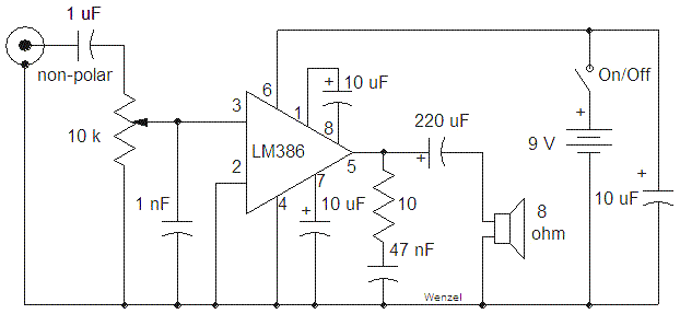
Build A Great Sounding Audio Amplifier With Bass Boost From The Lm386

150w Mp3 Car Amplifier
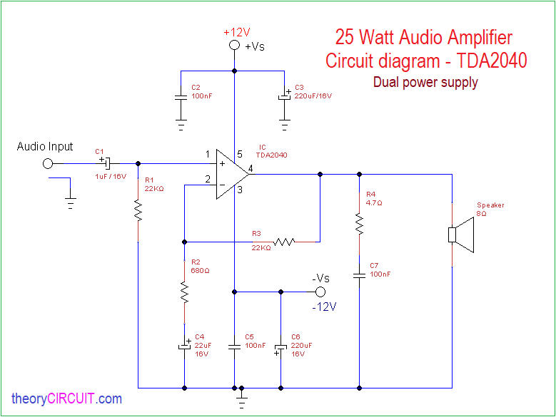
25 Watt Audio Power Amplifier Circuit
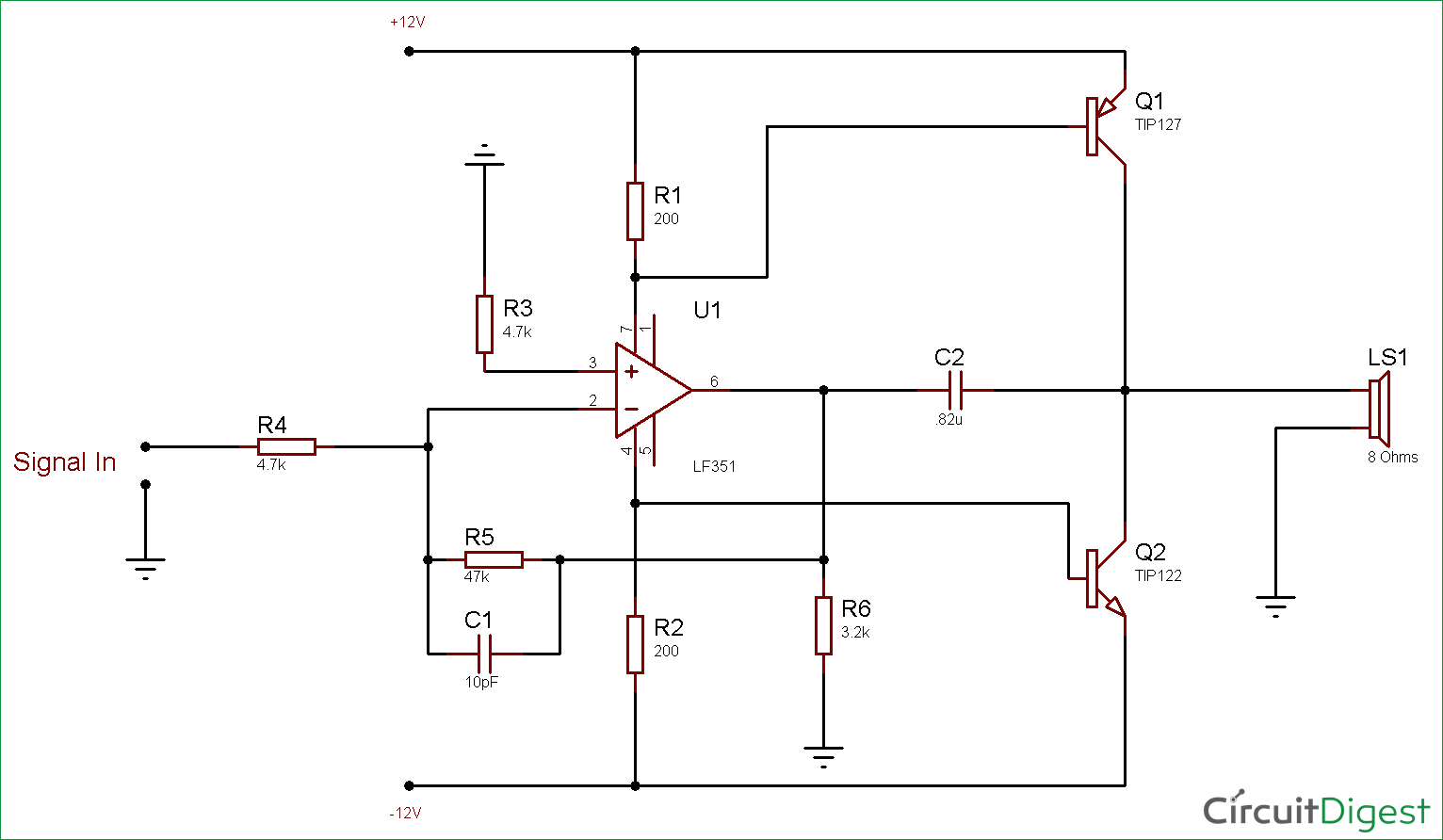
10 Watt Audio Amplifier Circuit Diagram Using Op Amp And Power Transistors
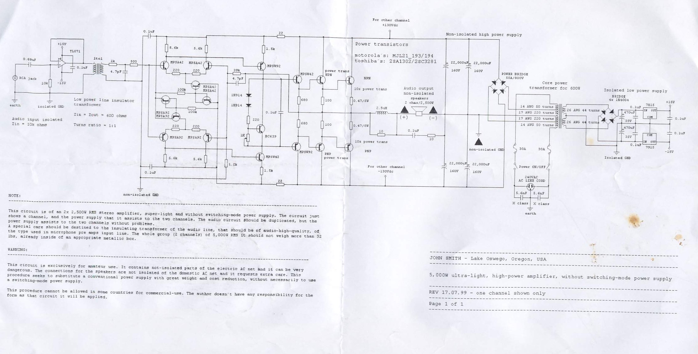
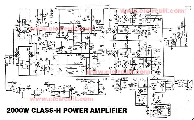
This circuit is of an 2x 2,500W RMS stereo amplifier, superlight and without switchingmode power supply The circuit just shows a channel, and the power supply that it assists to the two channels The audio circuit should be duplicated, but the power supply assists to the two channels without problems.

High voltage audio amplifier circuit diagram. 100W Audio Amplifier Circuit Diagram and Explanation The schematic for this 100 watt Audio Amplifier has a few stages At the beginning of the first stage amplification, a filter section blocks unwanted frequency noises This filter section is created using the R3, R4, and C1, C2. Mono high power amplifier circuit is actually powerful, output about 1400 W, but if this high power amplifier circuit is doubled and you want to create stereo power amplifier, this high power amplifier circuit the necessary components and PCB requires twofold So if the stereo high power amplifier 2 X 1400W Power Output ( 2800W ) Power Amplifier Circuit Diagram is still less by looking at. They are not tested by us.
High Power L440 Double IC Stereo Audio Amplifier with Bass and Treble Control The L440 is a very popular dualchannel audio amplifier commonly used to build high power audio amplifiers. Mosfet audio amplifier Circuit diagram 10 watts mosfet amplifier Notes The circuit can be assembled on a vero board Use 30V DC for powering the circuit Do not expect much performance from this amplifier Capacitors C3, C4, C5 must be rated 50V and C2 can be 10V Use a 8 ohm 15W speaker as the load Go to Top of List 3 50 Watts Mosfet Amplifier. Circuit diagram Parts P1 22K LogPotentiometer (Dualgang for stereo) P2 100K LogPotentiometer (Dualgang for stereo) R1 0R 1/4W Resistor R2,R4,R8 4K7 1/4W Resistors R3 500R 1/2W Trimmer Cermet R5 K 1/4W Resistor R6,R7 47K 1/4W Resistors R9 10R 1/2W Resistor R10 R22 4W Resistor (wirewound) C1,C8 470nF 63V Polyester Capacitor.
A voltage amplifier circuit is a circuit that amplifies the input voltage to a higher voltage So, for example, if we input 1V into the circuit, we can get 10V as output if we set the circuit for a gain of 10 Voltage amplifiers, many times, are built with op amp circuits However, with a transistor and the correct biasing, we can produce the. This circuit is under, audio, vacuum tubes, Vented 2a3p 2a3pp 15w Tube Amplifier circuit diagram l Elliot vented 2A3PP line, is also very simple, the key is the quality of the output of cattle Use 3KPP output cattle, fixed bias (a 62V), output power 15W 2A3PP suited for th. Class D power amplifier Class D power amplifier is a type of audio amplifier were the power handling devices are operated as binary switches Since the power handling devices (MOSFETS) works as perfect binary switches, no time is wasted in between the transition of stages and no power is wasted in the zero input condition.
Bridge Amplifier The circuit given below is a bridge audio amplifier circuit using IC TD935 Description TD935 is 2x15W high quality audio amplifier IC from Siemens The. They are not tested by us. 2 thoughts on “ 3 simple audio amplifier circuit diagram ” June 27, 19, 347 pm Brokya mein aapke projects banake youTube mein share kar sakta humera ek youTube channel haiagar aap kaho to mein ye projects banake share krna chahta hui am waiting for u r reply.
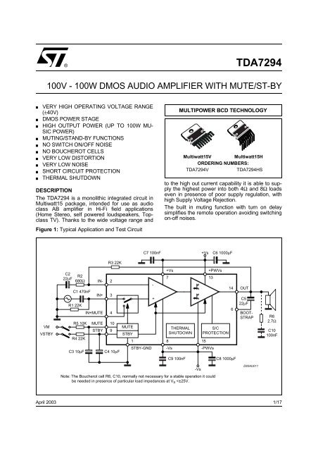
The driver circuit is described as a high voltage opamp (Operational amplifier) At 10kHz most opamps in audio circuits will have a gain of approx 1,000 and at 1MHz will have unity gain The right pic shows an average $1 opamp is capable of a flat response to 100kHz with a gain of 100. TD294 is a monolithic integrated circuit in Multiwatt15 package, with high output power (up to 100W) intended for TD030 Audio Amplifier Circuits P Marian. This power amplifier circuit is a 1600W at 8 Ohm mono circuit that uses transistors as an amplifier Almost same with 2800W high power amplifier circuit, For stereo power amplifier circuit, you can use this circuit 2x and will issue a power of 30W Let us first see the circuit schematic below.
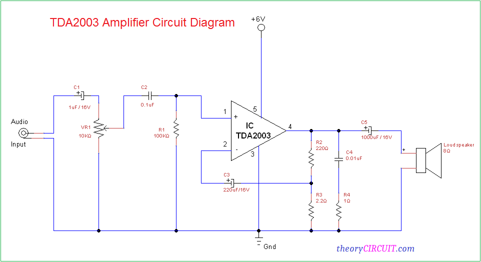
APPLICATIONS large output voltage swing, high current capability, and a very wide supply range The amplifier is • High Performance Audio Systems internally compensated and stable for gains of 10 or • Bridge Amplifiers greater • Stereo Phonographs • Servo Amplifiers • Instrument Systems Connection Diagram Figure 1 NDH0005D, KC0005A,. We do not guarantee success in building devices using our diagrams!. Circuit Diagram Working Explanation The TD003 amplifier IC delivers a 7 Watt output power using a 12V, 500mA power supply with a 4Ω speaker TD003A is a 5pin audio amplifier IC The pins 5 & 3 power the Amplifier IC, and the audio signal to be amplified is given in through pin 1 which is the noninverting input.
Mosfet audio amplifier Circuit diagram 10 watts mosfet amplifier Notes The circuit can be assembled on a vero board Use 30V DC for powering the circuit Do not expect much performance from this amplifier Capacitors C3, C4, C5 must be rated 50V and C2 can be 10V Use a 8 ohm 15W speaker as the load Go to Top of List 3 50 Watts Mosfet Amplifier. High voltage, highside floating current sensing circuit using current output current sense amplifier Lowdrift, lowside, bidirectional current sensing circuit with integrated precision gain resistors. High voltage, highside floating current sensing circuit using current output current sense amplifier Lowdrift, lowside, bidirectional current sensing circuit with integrated precision gain resistors.
We do not guarantee success in building devices using our diagrams!. The driver circuit is described as a high voltage opamp (Operational amplifier) At 10kHz most opamps in audio circuits will have a gain of approx 1,000 and at 1MHz will have unity gain The right pic shows an average $1 opamp is capable of a flat response to 100kHz with a gain of 100. 3) LM386 Audio Power Amplifier – LM386 is a low voltage audio power amplifier IC It operates between a voltage range of 4 V to 12 V In this circuit, the IC is provided a bias voltage of 12 V This IC can drive a load having impedance in range from 4 ohms to 32 ohms.
An amplifier circuit diagram consists of a signal pickup transducer, followed by small signal amplifier(s), a large signal amplifier and an output transducer Initially, there are two type of amplifier circuit diagram is in practical ie voltage amplifier circuit and power amplifier circuit. 3) LM386 Audio Power Amplifier – LM386 is a low voltage audio power amplifier IC It operates between a voltage range of 4 V to 12 V In this circuit, the IC is provided a bias voltage of 12 V This IC can drive a load having impedance in range from 4 ohms to 32 ohms. You are in Audio circuit diagram category 0W audio amplifier Sound Level Meter Amplifier 2x30W with STK465 10W Mini Audio Amplifier Stereo Tube Amplifier 10W Audio Amplifier with Bassboost especially diagrams related to high voltage!.
You are in Audio circuit diagram category 0W audio amplifier Sound Level Meter Amplifier 2x30W with STK465 10W Mini Audio Amplifier Stereo Tube Amplifier 10W Audio Amplifier with Bassboost especially diagrams related to high voltage!. This outstanding 250 watt mosfet amplifier circuit can be used as a DJ amplifier in concerts, parties, open grounds etc The design being symmetrical produces negligible distortions Let’s try to analyze the circuit details Referring to the circuit diagram, we see that the input stages primarily consists of two differential amplifiers. This circuit is not for a standard audio application The input signal is bandlimited.
This circuit is under, audio, vacuum tubes, Vented 2a3p 2a3pp 15w Tube Amplifier circuit diagram l Elliot vented 2A3PP line, is also very simple, the key is the quality of the output of cattle Use 3KPP output cattle, fixed bias (a 62V), output power 15W 2A3PP suited for th. 3) LM386 Audio Power Amplifier – LM386 is a low voltage audio power amplifier IC It operates between a voltage range of 4 V to 12 V In this circuit, the IC is provided a bias voltage of 12 V This IC can drive a load having impedance in range from 4 ohms to 32 ohms. At the time of amplifier circuit stanby, measure voltage contained in the R19 or R resistors and set at 150mV This high power audio amplifier circuit designed for high power amplification to provide peak power 2kW and 1,5kW continuously, so that this amplifier can drive your big speakers with fantastic.
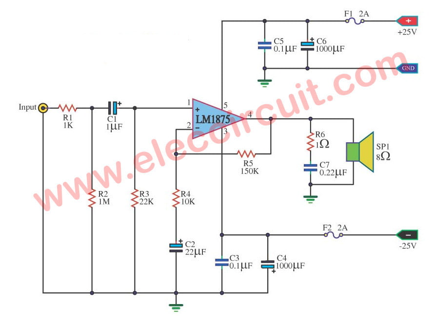
50W audio power amplifier circuit diagram Amplifiers Jun , 044 High quality exponential VCA Amplifiers Apr 17, 044 Selection of Integrated Circuit Audio Amplifiers Amplifiers 4 Potpourri of Transistor Audio Amplifier Circuits Amplifiers 1 16 Watt audio amplifier using pair of 8 watt LM3 audio amplifier chips Amplifiers. You are able to build this circuit using a minimal price This circuit is suitable for inexpensive sound amplification requirements in electronics for example preamplifier for FM audio receivers Circuit diagram Audio amplifier circuit Components required Resistors 1K, and 100K 1/4 watt Capacitors (10uF). The 50 watt audio amplifier circuit shown below is designed based on the application diagram from the data sheet of LM3876 Some modifications are made on the original circuit for improving the performance The bipolar electrolytic capacitor C7 is the input DC decoupling capacitor R4 is the input resistance.
Description The circuit is based around {LM4702} manufactured by NATIONAL semiconductors & {MJMJ} by ON semiconductors It is a high fidelity audio power amplifier Designed for demanding consumer and proaudio applications You can also use this circuit with AV receivers, Audiophile power amps, Pro Audio High voltage industrial applications etc Amplifier output power maybe. The power amplifier circuit SOCL 504, Watt is one of a high power amplifier power circuit that can be used for field or outdor power amplifier so as to enable rental of your sound system either in high position in tweeter or line of midle or bass array on 15 inch or it could be on a sub low at 18 inches. Single Ended Class A 6V6 6J5 Valve (Vacuum Tube) Amplifier Circuit This is my first successful vacuum tube project The output of this small amplifier in which a 6V6GT output pentode is connected as triode is about 45 watts.
Recent searches W Guitar Amplifier, 1000 rms power amp, schema telehone mobil siemens c25, Geomagnetic field detector, preamplifier subwover, 1phase rectifier, data, genrator avr 50~60hz, simple radio, high voltage detector cercuit,. 100W Audio Amplifier Circuit Diagram and Explanation The schematic for this 100 watt Audio Amplifier has a few stages At the beginning of the first stage amplification, a filter section blocks unwanted frequency noises This filter section is created using the R3, R4, and C1, C2. 2 thoughts on “ 3 simple audio amplifier circuit diagram ” June 27, 19, 347 pm Brokya mein aapke projects banake youTube mein share kar sakta humera ek youTube channel haiagar aap kaho to mein ye projects banake share krna chahta hui am waiting for u r reply.
LM386 Audio Amplifier Circuit with PCB It was my first mini audio amplifier Many people also use it Because it’s easy to build and this IC always popular And suitable for 9V battery 2W2W Stereo using 3 LM386 Here is an LM386 stereo audio amplifier circuit, 2 watts Using 3 ICs in a bridge model. 1600W High Power Amplifier Circuit Diagram In the buffer circuit coupled with opamp ic 4558, supplied 15VDC voltage, circuit power supply you can see in the picture is flavored transistor D313 and B507 Driver circuit using transistor MJ40 MJ50 For use transformer, it's using one transformer by one circuit mono. TD030 IC Amplifier Circuit Diagram The required components used in TD030 IC subwoofer circuit are audio jack pin, IC TD030 IC, Resistors three100K, one 47 K and one0 ohm, capacitors like one100 mf, two01 mf, two22 mf & one22mf, one In4007 diode, one speaker, 12v battery, and one variable resistor with 22k value.
The amplifier circuit diagram shows a 25W * 2 stereo amplifier You can also make a 5W mono amplifier out of it (Check out the TE025 datasheetfor more information on that) On the input side, you should use a dual potentiometer. And you need to make sure that the capacitors that you are using for filtering are rated for high voltage, at least 100VAC (more doesn't hurt) The rest of the capacitors in the design also need to have an appropiate voltage rating I designed this amplifier for an output power of about W You should use a bipolar power supply with ±30V. 50W audio power amplifier circuit diagram Amplifiers Jun , 044 High quality exponential VCA Amplifiers Apr 17, 044 Selection of Integrated Circuit Audio Amplifiers Amplifiers 4 Potpourri of Transistor Audio Amplifier Circuits Amplifiers 1 16 Watt audio amplifier using pair of 8 watt LM3 audio amplifier chips Amplifiers.
This power amplifier circuit is a 1600W at 8 Ohm mono circuit that uses transistors as an amplifier Almost same with 2800W high power amplifier circuit, For stereo power amplifier circuit, you can use this circuit 2x and will issue a power of 30W Let us first see the circuit schematic below. S audio amplifier circuits, ic amplifier Electronics Circuits PCB spark gap @Bülent NUR forwarded by my teacher PCB spark gap videosu review, especially in power electronics PCB designs contains useful information for possible leakages on the system high voltage spark gap for a method to be applied to minimize damage thanks @Bulent. LM4702 general description The LM4702 is a high fidelity audio power amplifier driver designed for demanding consumer and proaudio applications Amplifier output power may be scaled by changing the supply voltage and number of output devices The LM4702 is capable of delivering in excess of 300 watts per channel single ended into an 8 ohm.
In this tutorial, I’ll show you how to build a great sounding audio amplifier with the LM386 Low Voltage Audio Power AmplifierI built about a dozen different audio amplifier circuits with the LM386 but most of them had way too much noise, popping, and other interference. Circuit Diagram Working Explanation The TD003 amplifier IC delivers a 7 Watt output power using a 12V, 500mA power supply with a 4Ω speaker TD003A is a 5pin audio amplifier IC The pins 5 & 3 power the Amplifier IC, and the audio signal to be amplified is given in through pin 1 which is the noninverting input.
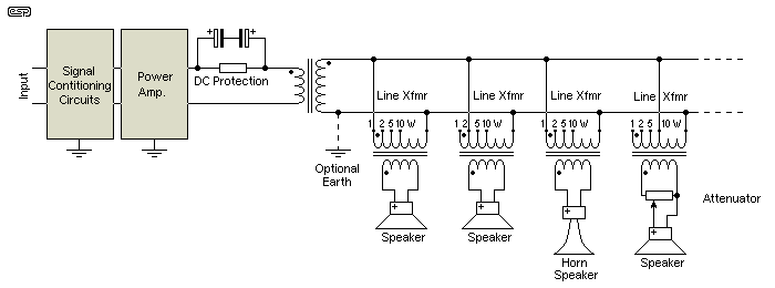
High Voltage Audio

Stk4231 Ii 100w 100w Stereo Audio Amplifier Circuit Diagram 100 Watts Amplifier
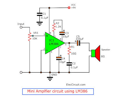
Lm386 Audio Amplifier Circuit With Pcb
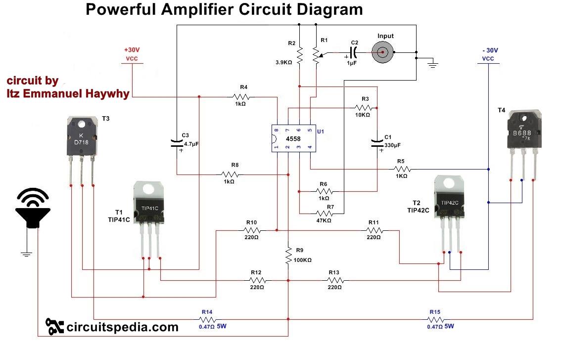
How To Make Audio Power Amplifier Circuit Electronic Projects Design Ideas Electronics Lab Com Community
Small Audio Power Amplifier Using 3 Transistors Deeptronic
60 Watt Audio Power Amplifier Circuit Diagram Circuit Diagram

Pin On Hubby Project
5000w Ultra Light High Power Amplifier Electronics Lab Com

0w Hybrid Audio Amplifier Circuit
300w Ocl Power Amplifier Electronic Schematic Diagram
Audio Amplifiers
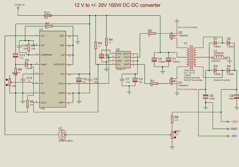
How To Build Automotive 12v To v Converter For Audio Amplifier Circuit Diagram
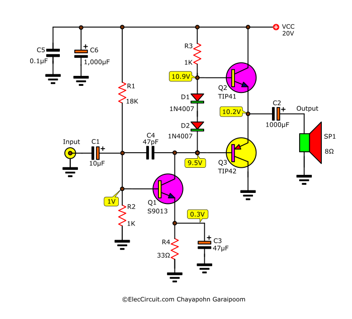
0 Watt Mosfet Amplifier Circuit To 300w On Class G Projects Circuits

Audio Amplifier 30w

Watt Power Amplifier Schematic Electronic Circuit Wiring Diagram

5000w High Power Amplifier Audio Circuits Electronic Circuit

High Voltage 3 Watt Audio Power Amplifier Circuits Projects

High Power Amplifier Circuit Diagram Circuit Diagram Images Circuit Diagram Power Amplifiers Audio Amplifier

Low Voltage Audio Amplifier
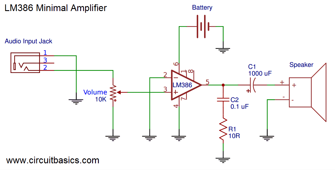
Build A Great Sounding Audio Amplifier With Bass Boost From The Lm386
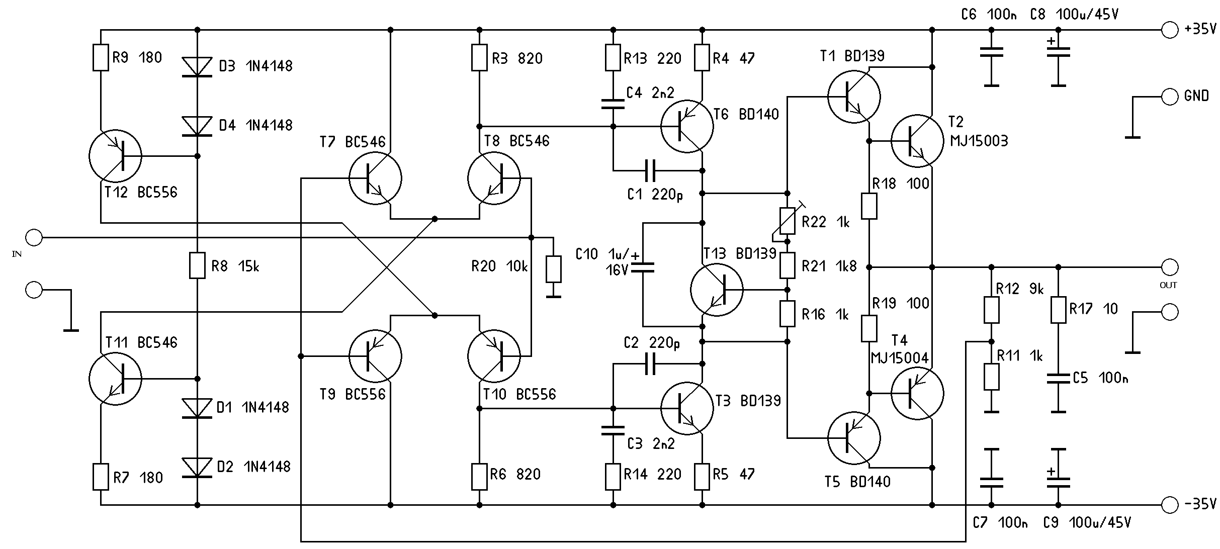
100 Watt Hifi Amplifier Circuit And 5 Band Equalizer Electronics Projects Circuits

1400w High Power Audio Amp Schematic Audio Amplifier Circuit Diagram Electronics Circuit
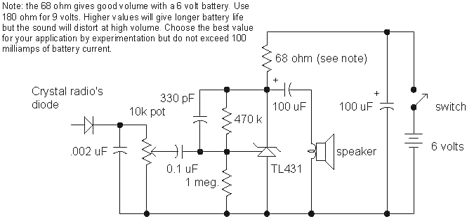
Audio Amplifiers

Experiment Transistor Circuit Design
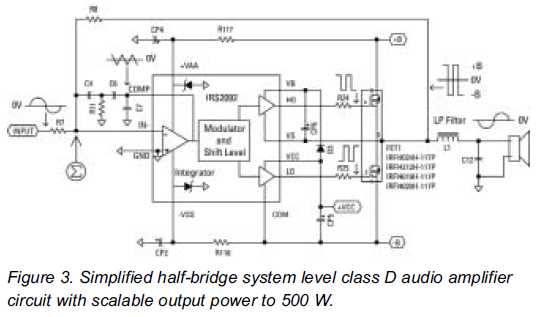
Results Page 543 About 115 V Dc Power Supply Searching Circuits At Next Gr

12 Watt Audio Amplifier Circuit Using Tda2616 Power Amplifier
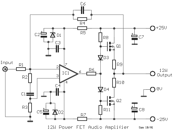
Fet 12w Audio Power Amplifier Circuit Diagram And Instructions
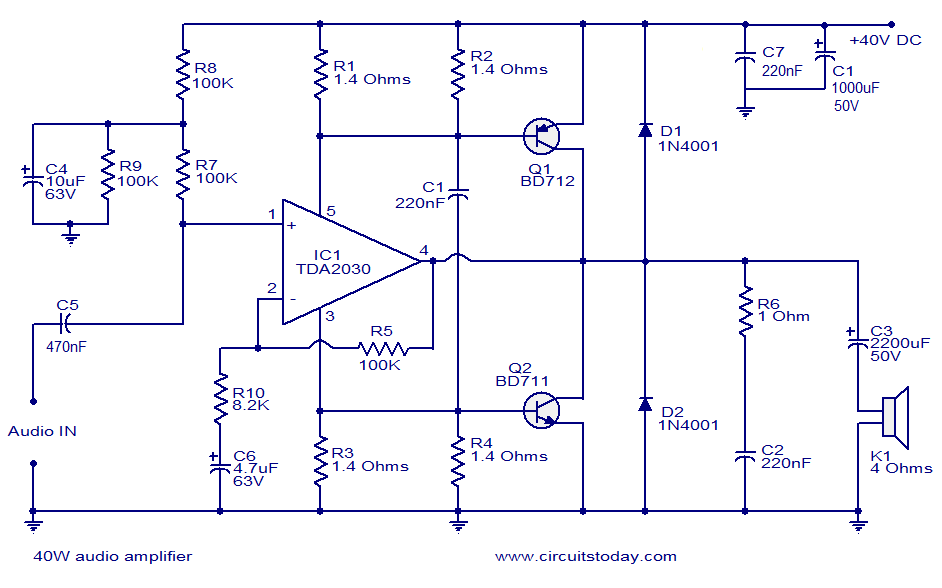
40w Audio Amplifier
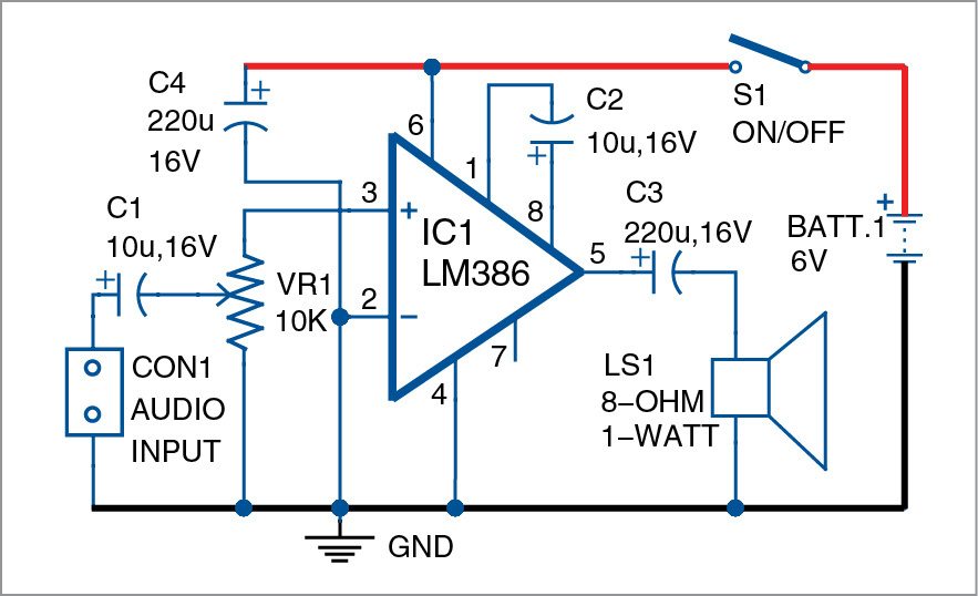
Lm386 Based Audio Amplifier Full Project With Circuit Available
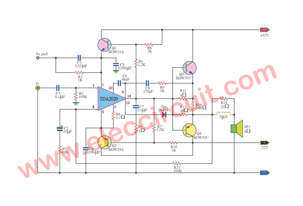
Tda Ocl Hi Fi Power Amplifier w To 80w Eleccircuit Com

Tda1514 40 Watt Audio Amplifier Circuit

Class A Amplifier Is A Class A Transistor Amplifier
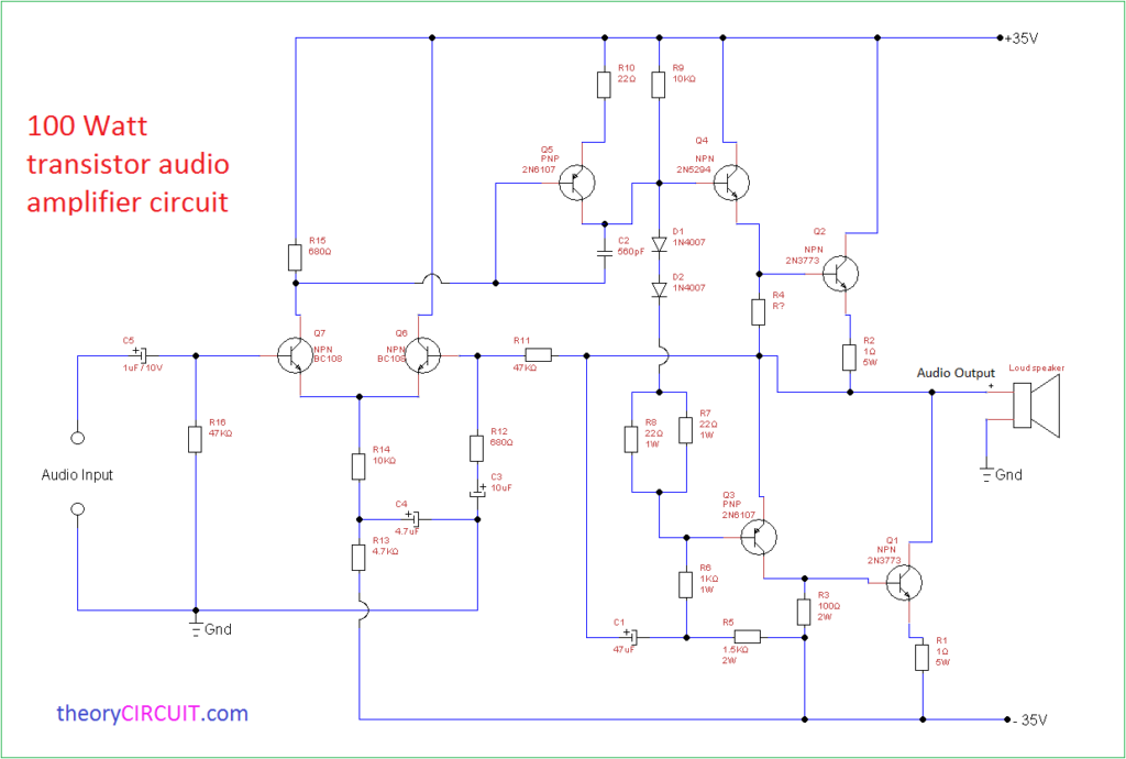
100 Watt Transistor Audio Amplifier Circuit
Tda03 Amplifier Circuit Diagram
Transistor Amplifier Circuit With Diagram For 12 Watts
How To Build Stereo Tube Amplifier Circuit Diagram
Lm1875 Datasheet 25w Hifi Audio Amplifier Circuit Eleccircuit Com
Tda7294 100v 100w Dmos Audio Amplifier With Mute St By 3volt

50 Watt High Power Mosfet Amplifier Diyaudio

Amplifier Circuit Diagram Power Amplifier Voltage Amplifier
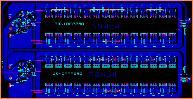
High Power 20w Amplifier Circuit Electronics Projects Circuits

Bootstrapping Your Op Amp Yields Wide Voltage Swings Edn
Q Tbn And9gcsfv Kzde 2rhnv3rxz S5jnneee3u2f4w93odtregqdmm Onih Usqp Cau

Audio Amplifier Circuit Using Two 108 Transistors
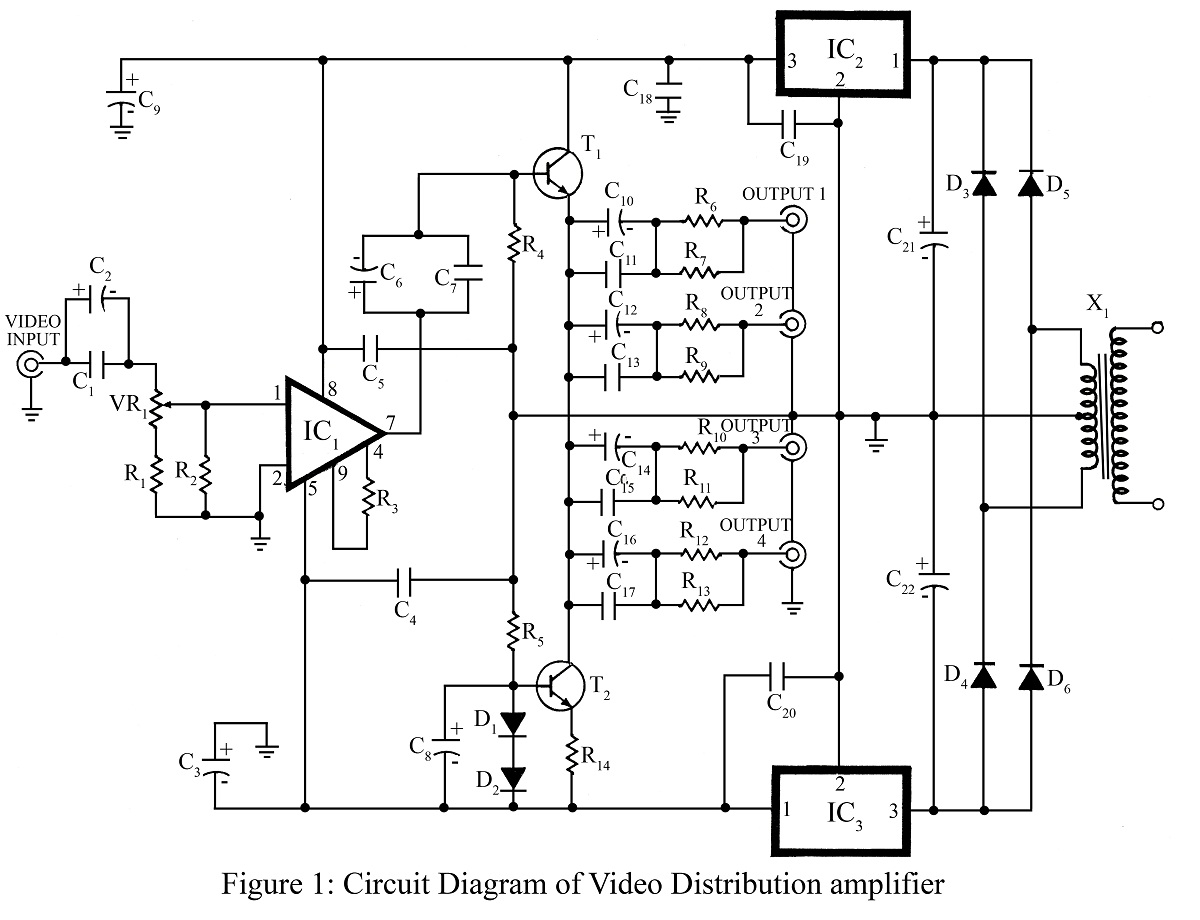
Video Amplifier Circuit Video Circuits Next Gr
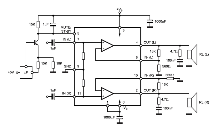
Tda7265 Stereo Audio Amplifier Ic Pinout Features Datasheet

This 0 Watt High Quality Power Audio Amplifier Will Give You Top Class Quality For Loudspeaker 4 8 Ohm Frequ Audio Amplifier Circuit Diagram Diy Amplifier
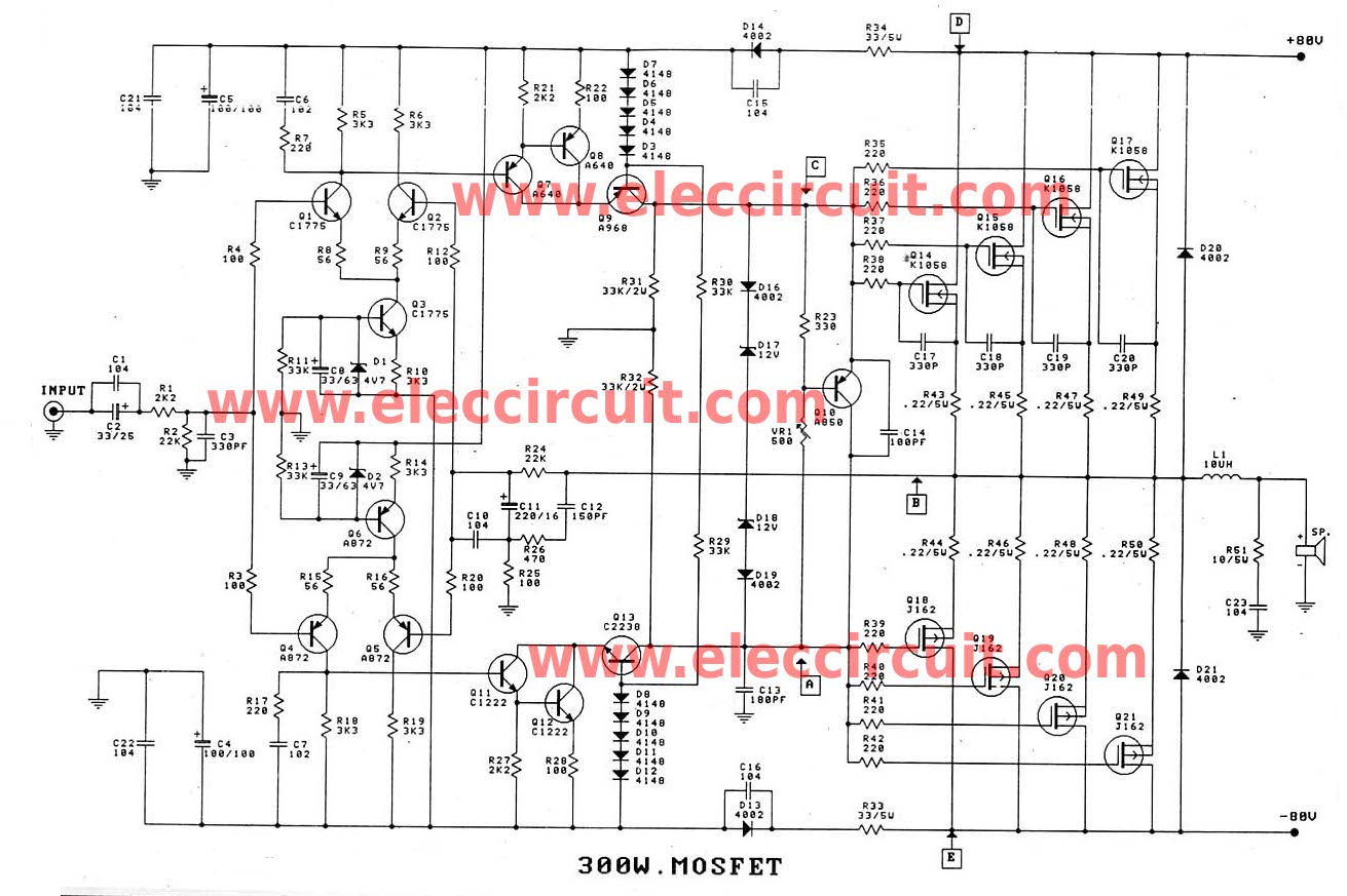
300 10w Mosfet Amplifier For Professionals Projects Circuits
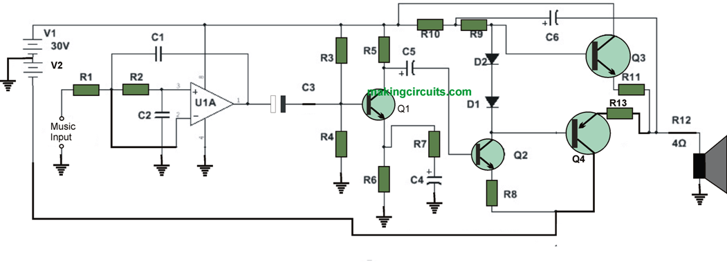
Subwoofer Amplifier Circuit High Power

Watt Power Amplifier Schematic Electronic Circuit Wiring Diagram

300 Watt Mosfet Real Hi Fi Power Amplifier Eeweb

Class A Amplifier Is A Class A Transistor Amplifier
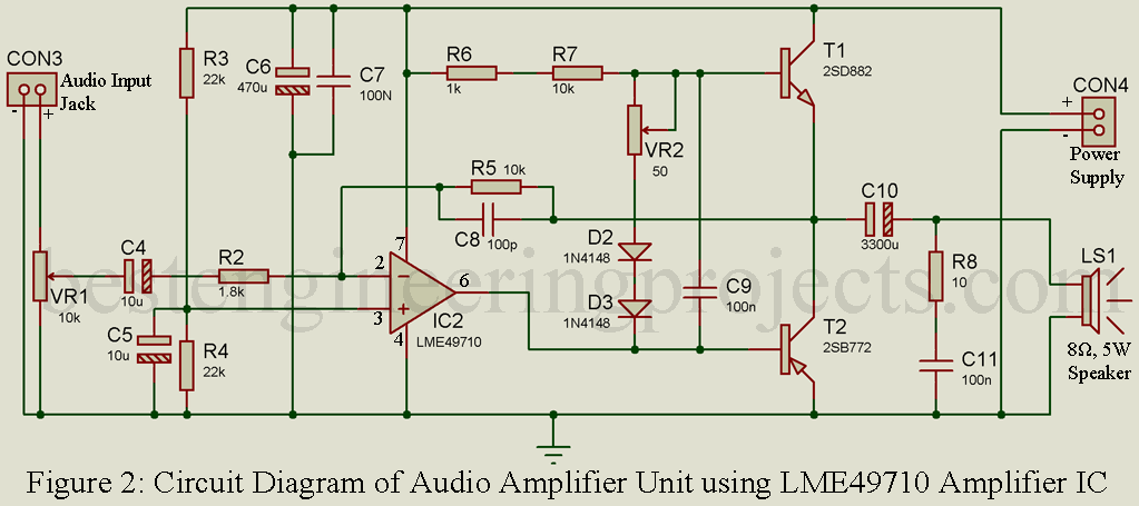
Best Audio Amplifier Circuit Engineering Projects

Tda30 Audio Amplifier Circuit Diagram
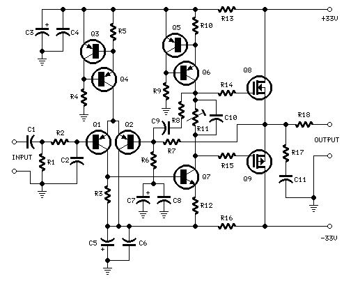
25w Mosfet Audio Amplifier Circuit Diagrams Schematics Electronic Projects
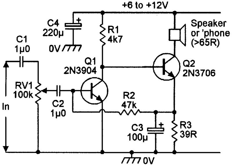
Bipolar Transistor Cookbook Part 7 Nuts Volts Magazine
Uu Diva Portal Org Smash Get Diva2 Fulltext01 Pdf
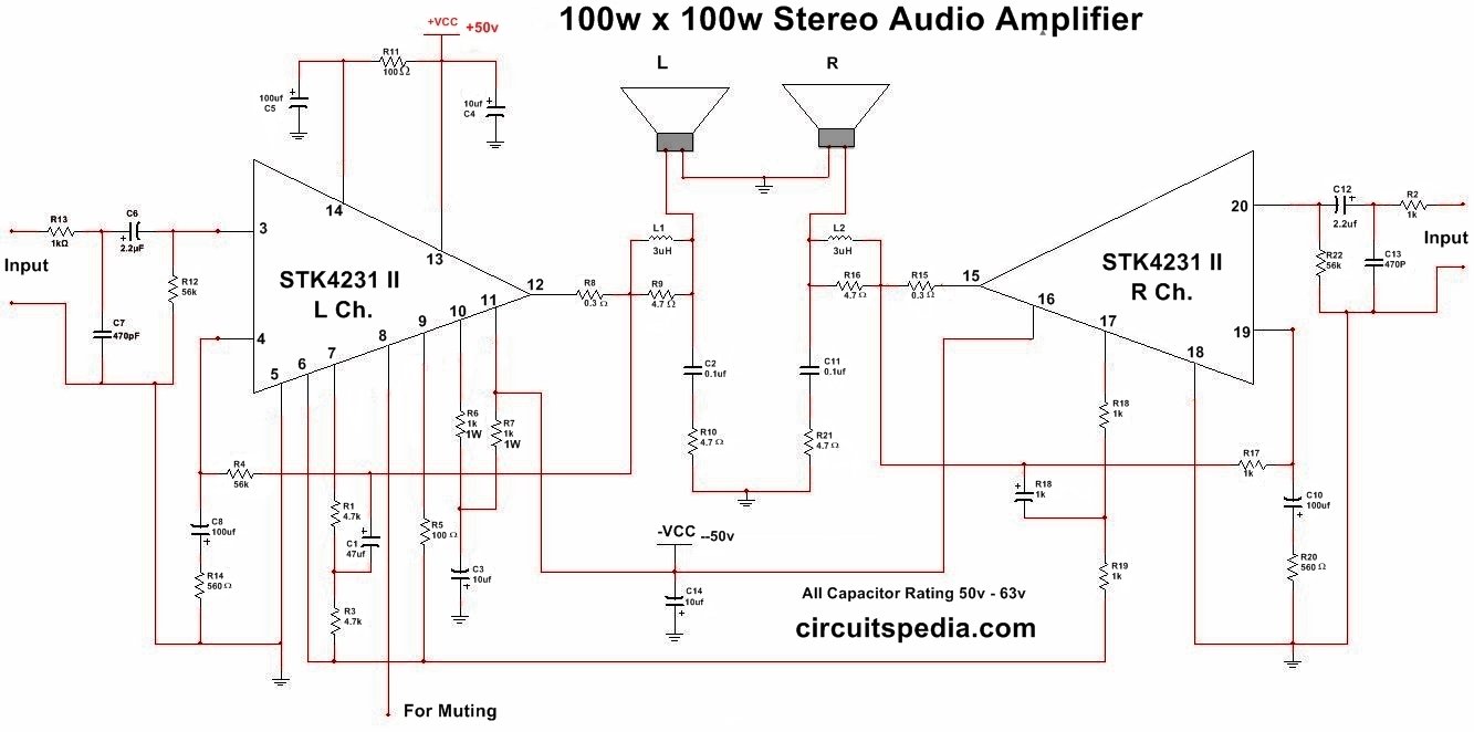
Stk4231 Ii 100w 100w Stereo Audio Amplifier Circuit Diagram 100 Watts Amplifier
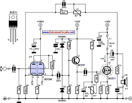
Simple Hybrid Audio Amplifier Circuit Diagram
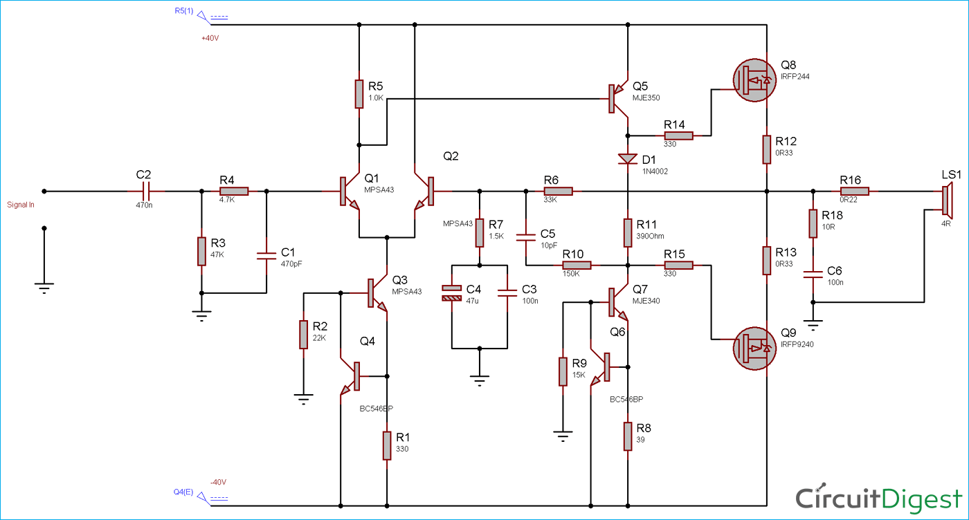
100 Watt Power Amplifier Circuit Diagram Using Mosfet
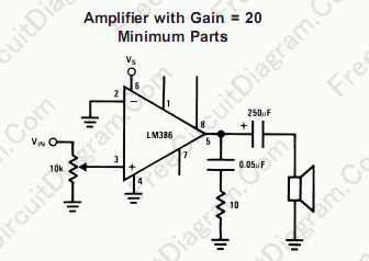
Small Low Voltage High Quality Audio Amplifier Electronic Circuit Diagram
1

Stereo Mini Amplifier With Tea25b Schematic Circuit Diagram

Pin On Hubby Project
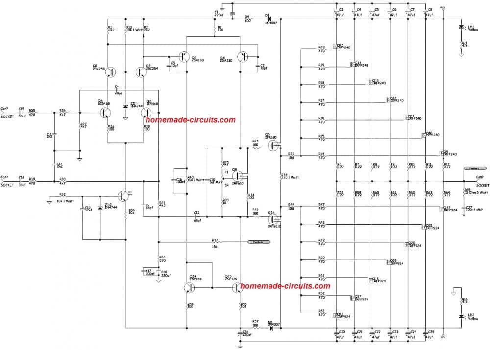
1000 Watt To 00 Watt Power Amplifier Circuit Homemade Circuit Projects
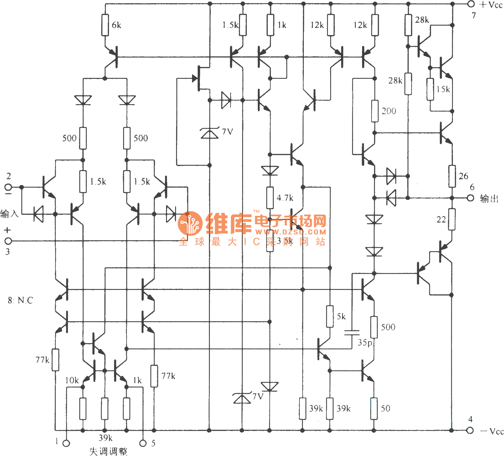
High Voltage Operational Amplifier Circuit With Internal Compensation Amplifier Circuit Circuit Diagram Seekic Com
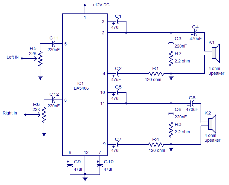
5x2 Watt Ba5406 Stereo Amplifier Operates From 9v Dc Low Distortion
Q Tbn And9gcqwn1 Lk4cvxhzme2v8p 5tcuzgzrsuuct0pmrraemcov E E G Usqp Cau

High Performance Power Amplifier 400 Watt Power Amplifiers Audio Amplifier Circuit Diagram

10 Watt Audio Amplifier Using Lm1875 Full Electronics Project

0w Audio Amplifier Circuit Diagrams Schematics Electronic Projects

High Power 20w Amplifier Circuit Electronics Projects Circuits

How To Build 0w Audio Amplifier Circuit Diagram

High Power 250 Watt Mosfet Dj Amplifier Circuit Homemade Circuit Projects

Schematic Diagram Of The High Voltage Amplifier Circuit Each Printed Download Scientific Diagram
Q Tbn And9gctqk7oear0uzzgva8ogkawfunsrrigljg1k2nnbeuabdmwhykol Usqp Cau
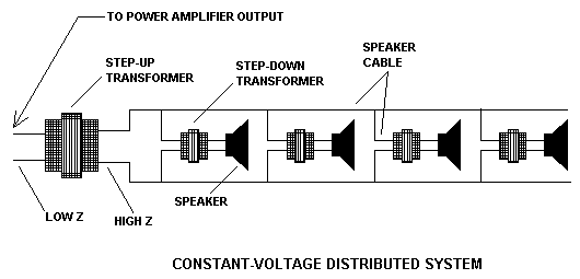
Advantages Of Direct Crown Audio Professional Power Amplifiers

Class B Audio Amplifier Analog Integrated Circuits Electronics Textbook
Powerful 00w Power Amplifier Class H Electronic Circuit
Audio Power Amplifier Circuit Using Hi Fi Audio Amplifier Ic Tda2613
Audio Amplifiers
2sc50 2sa1943 Amplifier Circuit Diagram Soldering Mind
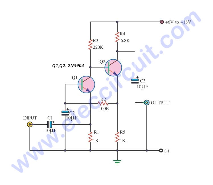
Simple Audio Amplifier Circuit Diagram Using Transistor Eleccircuit Com

Schematic Diagram Of The High Voltage Amplifier Circuit Each Printed Download Scientific Diagram

Super Circuit Diagram High Gain And Fidelity Audio Amplifier Circuit Diagram

Class B Audio Amplifier Analog Integrated Circuits Electronics Textbook
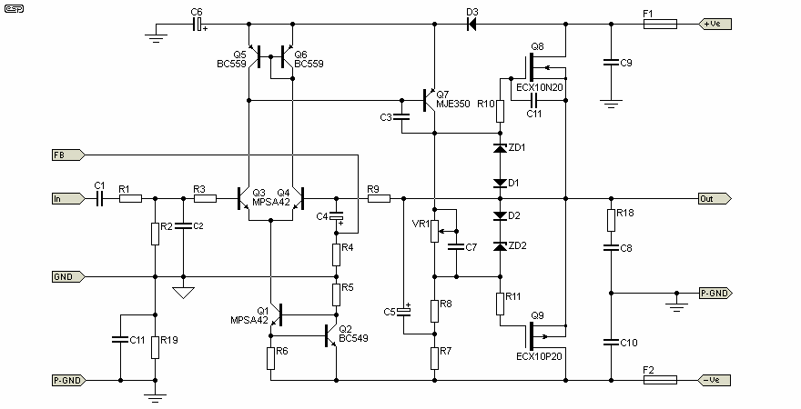
Project 101 High Fidelity Lateral Mosfet Power Amplifier
3 5 Watt Class A Audio Amplifier Red Page80

How To Make 00w Amplifiers Circuit Diagram At Home Youtube
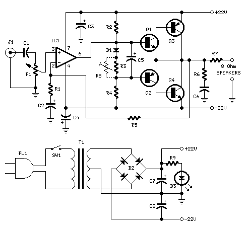
18w Audio Amplifier Circuit Diagrams Schematics Electronic Projects
2
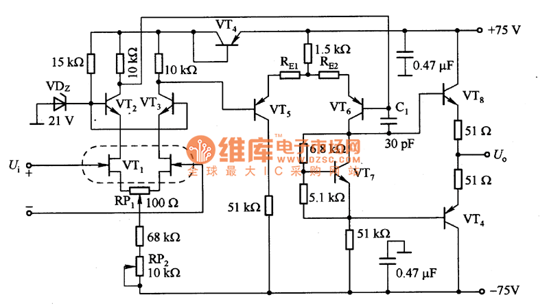
The High Voltage Input Fet Power Amplifier Circuit Diagram Amplifier Circuits Audio Amplifier Circuit Circuit Diagram Seekic Com

High Voltage Amplifier Uses Simplified Circuit Edn
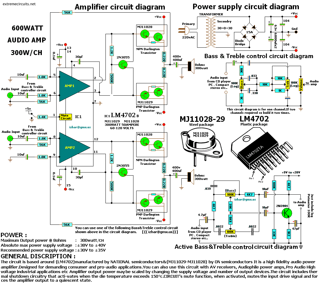
600w Audio Amplifier Electronics Lab Com
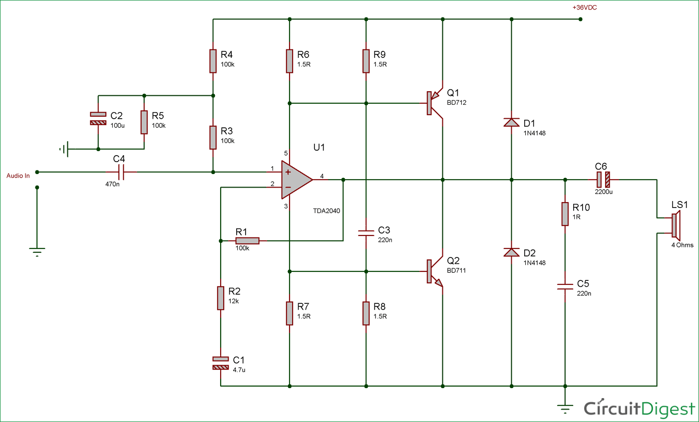
40 Watt Audio Amplifier Circuit Diagram Using Tda40 And Transistor Pair

High Voltage Regulator Schematic Circuit Diagram
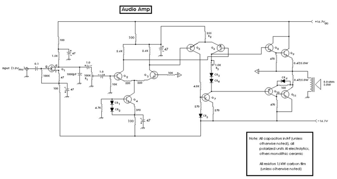
How To Build Speaker Box Audio Amp Circuit Diagram

3000w Stereo Power Amplifier Circuit Electronic Circuit Hifi Amplifier Audio Amplifier Electronics Circuit


