Motor Dc Diagram

Series Wound Dc Motor Or Dc Series Motor Electrical4u

Dc Motor Starters And Their Circuit Diagram Electrical Academia
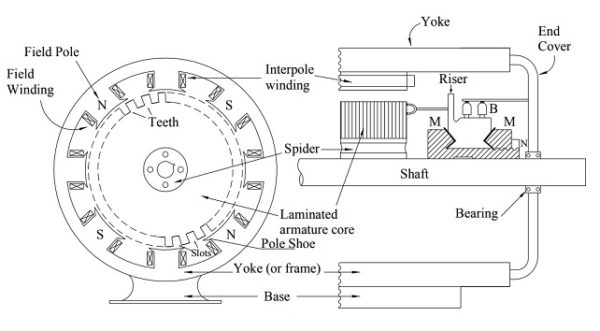
Construction Of Dc Motor Electrical Concepts

Working Or Operating Principle Of Dc Motor Electrical4u

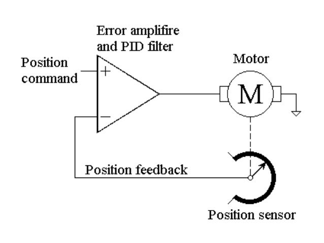
Dc Servo Motors Theory Of Dc Servo Motor Electrical4u

Block Diagram Of Electromechanical Systems Dc Motor Dademuchconnection
Hint it is very simple, and for large electric motors it involves the use of a shunt resistorModify this circuit diagram to include a meter that provides indirect indication of motor torque.

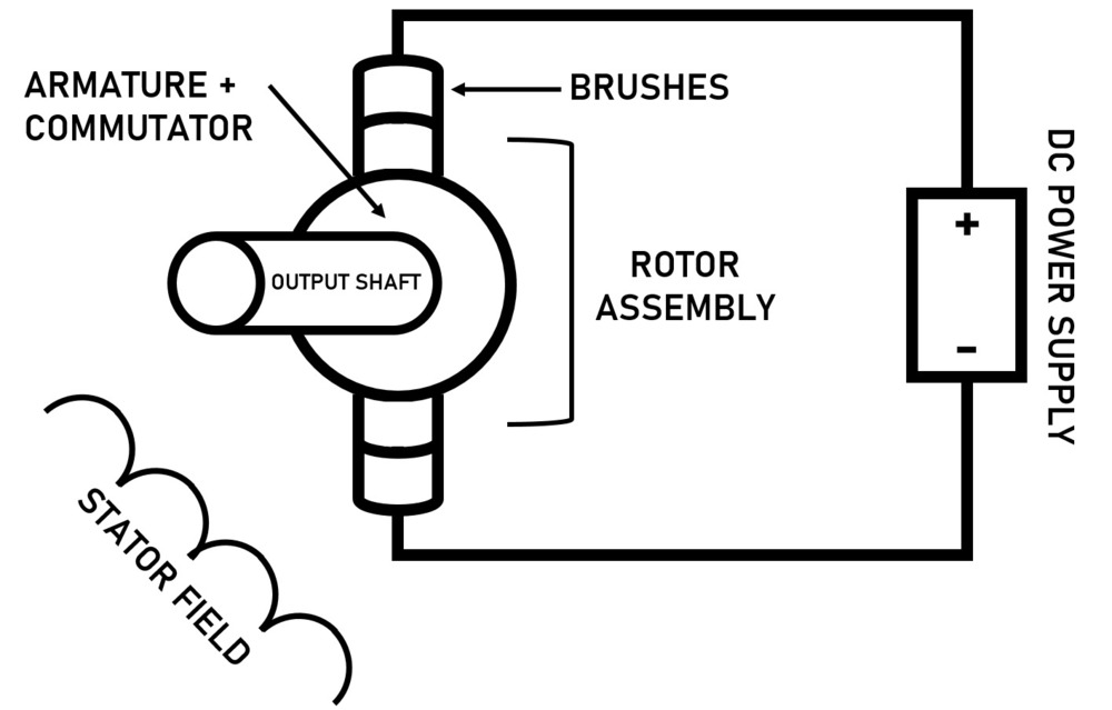
Motor dc diagram. To understand the DC motor in details lets consider the diagram below, The circle in the center represents the direct current motor On the circle, we draw the brushes On the brushes, we connect the external terminals, through which we give the supply voltage. 5V I 5V LWTL DC Motor!. P55n Mosfet (you can use any mosfet)50k Potentiometer10k Resistor12 Volt Power SupplyCircuit Diagram http//growamiscom/howtomakeanuniversaldcmotors.
A Universal Electric Motor is designed to operate on either alternating current or direct current (AC/DC) It is a series wound motor It is provided with a field winding on the stator which is connected in series with a commutating winding on the rotor Commonly manufactured in fractional horsepower sizes. The Dc Motor Types & Dc Motor is a Mechanism by which Electrical Energy is Converted into Mechanical EnergyBoth in principle and in design, the DC motor is the reverse of a DC Generator Dc Motor Magnet?. DC Motor Connections Your motor will be internally connected according to one of the diagrams shown below These connections are in accordance with NEMA MG1 and American Standards Publication 06 1 1956 Use figure 1 if your motor has a single voltage shunt field.
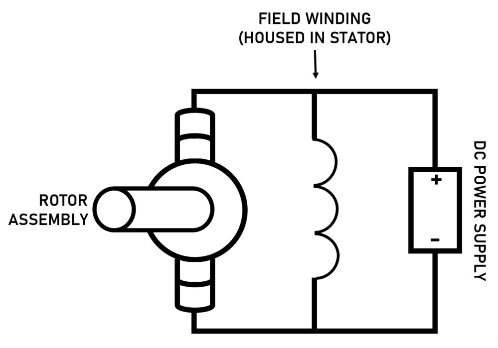
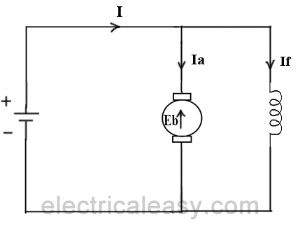
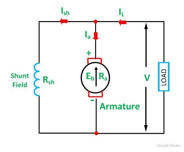
Connect your motor supply voltage here, maximum of 35V DC Remove 12V jumper if >12V DC GND 5V output if 12V jumper in place, ideal for powering your Arduino (etc) DC motor 1 enable jumper Leave this in place when using a stepper motor Connect to PWM output for DC motor speed control IN1 IN2 IN3 IN4 DC motor 2 enable jumper Leave this. Difference Between AC and DC Motor The AC Motor and the DC Motor are differentiated on the various factors like the source or the nature of the power used in the motor The commutation process, types, starting of the motor, a number of terminals Applications of the motor, usage of brushes and the maintenance cost of the motor. A DC shunt motor (also known as a shunt wound DC motor) is a type of selfexcited DC motor where the field windings are shunted to or are connected in parallel to the armature winding of the motor Since they are connected in parallel, the armature and field windings are exposed to the same supply voltageThough there are separate branches for the flow of armature current and field current.
We know that Dc Motor Magnetic lines of force travel from North pole to South pole The lines of force between these two poles in parallel. FIGURE 3 Fourpoint manual DC motor starter circuit diagram An automatic starter operates in a similar fashion, except that automatic relays short out sections of the starter resistance either by a time sequence or when the armature current drops to a selected value Automatic DC starters Figure 4 shows the automatic DC starter circuit diagram. BLDC motor stator winder coil winding machine from brushless dc electric motor diagram , sourceyoutubecom DRV07 Brushless DC Motor Controller Rev A Three from brushless dc electric motor diagram , sourcefdocumentsin So, if you’d like to receive all these fantastic photos regarding (Brushless Dc Electric Motor Diagram.
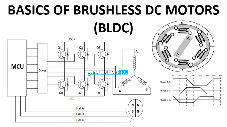
We know that Dc Motor Magnetic lines of force travel from North pole to South pole The lines of force between these two poles in parallel. Block diagram of a typical Brushless DC Motor control or drive system is shown in the following image This drive circuitry is often known as Electronic Speed Controller System or simply an ESC One common setup is called the Full Bridge Drive Circuit. Single Phase Motor Wiring Diagram With Capacitor – baldor single phase motor wiring diagram with capacitor, single phase fan motor wiring diagram with capacitor, single phase motor connection diagram with capacitor, Every electrical arrangement is made up of various unique pieces Each component ought to be placed and linked to different parts in particular manner.
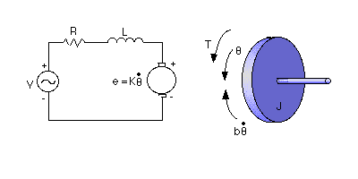
Question 1 How is it possible to electrically measure the torque output by a permanentmagnet DC motor?. Figure 1 (a) a basic electrical circuit of a DC motor and (b) a free body diagram of the motor rotor A basic equation governing the mechanical dynamics of the motor is (1) where is the rotor inertia, is the angle of rotation of the output shaft, is a mechanical torque developed in the motor rotor, is a disturbance torque, and is a damping. Hi, reader welcomes to another post in this post, we will discuss DC Shunt Motor Construction, Working Principle, Circuit Diagram Dc motor is such a motor that used dc power for its operationThis motor is used in such applications where dc power is commonly used The main parts of dc motor are stators which cover the internal parts of the motor and save motor from the external environment.
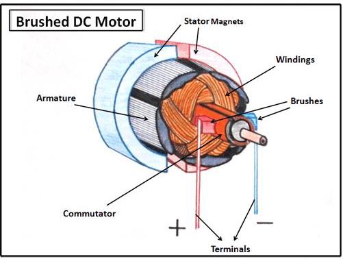
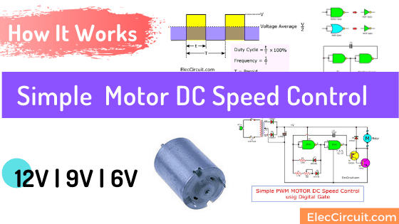
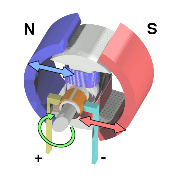
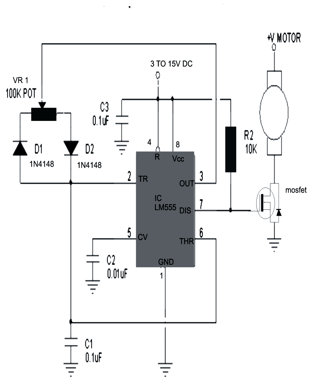
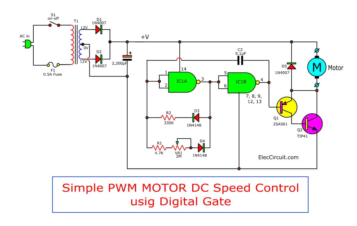
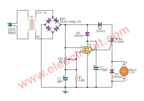
The Dc Motor Types & Dc Motor is a Mechanism by which Electrical Energy is Converted into Mechanical EnergyBoth in principle and in design, the DC motor is the reverse of a DC Generator Dc Motor Magnet?. In the above diagram, you can see two magnets in the motor The armature (or rotor) is an electromagnet, while the field magnet is a permanent magnet (the field magnet could be an electromagnet as well, but in most small motors it isn't in order to save power). We have 2 circuits diagram to show you The advantage of these 2 circuits is that if you have a 9V or 6V motor or battery, you can use it immediately Because we use a CMOS IC that can be used with a voltage of 3V to 15V First 4011 Motor DC Speed Control If you want to control the speed of a small 12V DC motor Before will see others circuit.
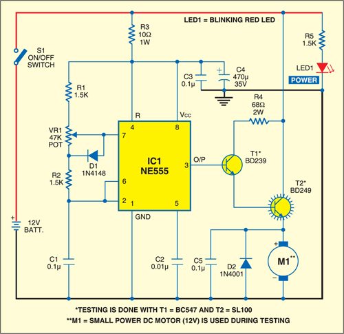
To understand the DC motor in details lets consider the diagram below, The circle in the center represents the direct current motor On the circle, we draw the brushes On the brushes, we connect the external terminals, through which we give the supply voltage. Here is a simple DC electric motor variable speed controller circuit that can be configured to control the sweep rate of automobiles’ windscreen wipers The circuit comprises a timer NE555 (IC1), mediumpower motor driver transistor BD239 (T1), highpower switching transistor BD249 (T2) and a few other discrete components. Question 1 How is it possible to electrically measure the torque output by a permanentmagnet DC motor?.
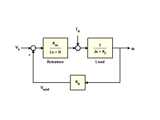
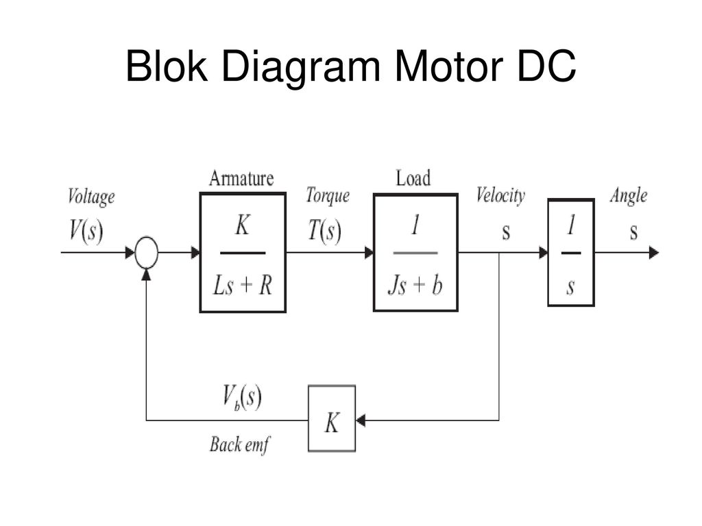
The torque produced by the motor is given by Where K T is the motor torque constant The back emf is proportional to the speed of the motor and hence The block diagram representation of the armature controlled DC servo motor is developed in Steps Usually the inductance of the armature winding is small and hence neglected Field Controlled. DC Motor Connections Your motor will be internally connected according to one of the diagrams shown below These connections are in accordance with NEMA MG1 and American Standards Publication 06 1 1956 Use figure 1 if your motor has a single voltage shunt field. The Dc Motor Types & Dc Motor is a Mechanism by which Electrical Energy is Converted into Mechanical EnergyBoth in principle and in design, the DC motor is the reverse of a DC Generator Dc Motor Magnet?.
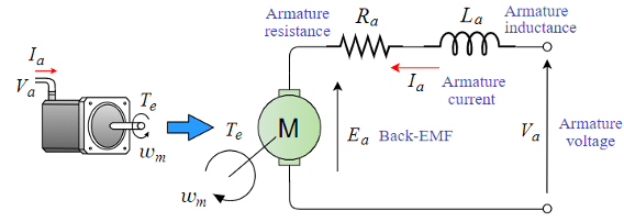
Working Principle of DC Motor Video gives an brief explanation in form of animation how does DC Motor works Also you can view working principle on eleme. Block Diagram and Transfer Function of DC Motor Armature Controlled DC Motor Consider the armature controlled dc motor and assume that the demagnetizing effect of armature reaction is neglected, magnetic circuit is assumed linear and field voltage is constant ie if=constant Let Ra=Armture resistance La=Armatureself inductancecausedbyarmatureflux ia=armaturecurrent if=fieldcurrent E. Wiring a DC motor and Universal motor for speed control I use a vacuum motor, electric lawn mower, and Treadmill motors to demonstration some cheap options.
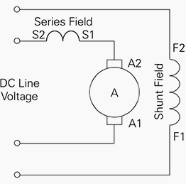
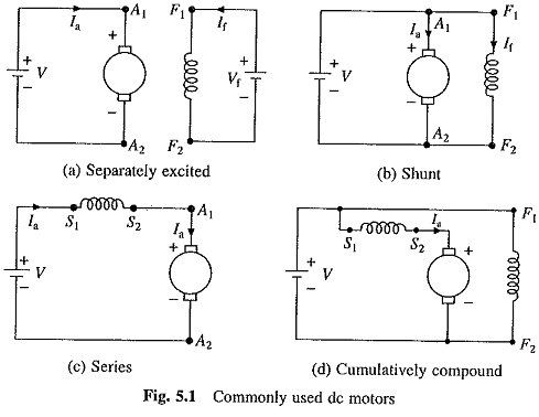
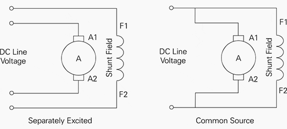
Windings have inductance and resistance!. Figure 3 – Diagrams of the various types of DC motor Parallel excitation (separate or shunt) The coils, armature and field coil are connected in parallel or supplied via two sources with different voltages in order to adapt to the characteristics of the machine (eg armature voltage 400 volts and field coil voltage 180 volts). On the manual mode, motor A and motor B can be controlled separately by selector switch On the automatic mode, motor A has to run for 3 minute then motor B comes on also Can you help me with the controlled diagram.
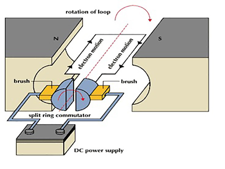
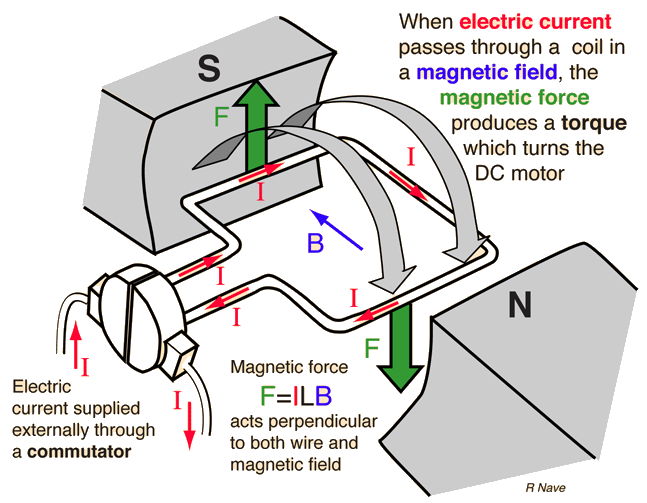
A DC motor is a mechanical rotating device which converts electrical energy into mechanical energy It is based on the principle of force acting on a current carrying wire in a magnetic field When an electric current is passed through the coil as shown in the diagram, equal and opposite forces act on opposite arms of the coil due to which the. Inductor stores electrical energy in the windings!. Working Principle of DC Motor Video gives an brief explanation in form of animation how does DC Motor works Also you can view working principle on eleme.
Wiring a DC motor and Universal motor for speed control I use a vacuum motor, electric lawn mower, and Treadmill motors to demonstration some cheap options. A DC motor is a mechanical rotating device which converts electrical energy into mechanical energy It is based on the principle of force acting on a current carrying wire in a magnetic field When an electric current is passed through the coil as shown in the diagram, equal and opposite forces act on opposite arms of the coil due to which the. On the terminal block 2 Always connect the power supply to the kit (5V16V DC) to the terminal block V and V3 You have a choice whether to use the same DC voltage to both the motor and the kit, or to use a different voltage for the motor (eg, it might be a 24V motor) from the 516V for the.
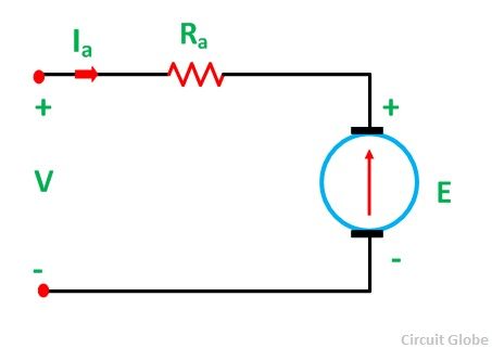
E a is the armature induced voltage I a is the armature current;. Block Diagram and Transfer Function of DC Motor Armature Controlled DC Motor Consider the armature controlled dc motor and assume that the demagnetizing effect of armature reaction is neglected, magnetic circuit is assumed linear and field voltage is constant ie if=constant Let Ra=Armture resistance La=Armatureself inductancecausedbyarmatureflux ia=armaturecurrent if=fieldcurrent E. There is no basic difference in the construction of a DC generator and a DC motor In fact, the same DC machine can be used interchangeably as a generator or as a motor Like generators, there are different types of DC motors which are also classified into shuntwound, serieswound and compoundwound dc motors DC motors are seldom used in ordinary applications because all electric supply.
Flyback diode or snubber diode!. DC Motor Model In this example, you model a DC motor driven by a constant input signal that approximates a pulsewidth modulated signal and look at the current and rotational motion at the motor output To see the completed model, open the PWMControlled DC Motor example Select Blocks to Represent System Components. To understand the DC motor in details lets consider the diagram below, The circle in the center represents the direct current motor On the circle, we draw the brushes On the brushes, we connect the external terminals, through which we give the supply voltage.
We need to provide a way to safely dissipate electrical energy when the switch is opened!. DC Series Motor Circuit Diagram In this motor, field, as well as stator windings, are coupled in series by each other Accordingly the armature and field current are equivalent Huge current supply straightly from the supply toward the field windings. Hint it is very simple, and for large electric motors it involves the use of a shunt resistorModify this circuit diagram to include a meter that provides indirect indication of motor torque.
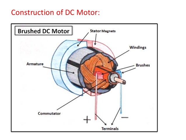
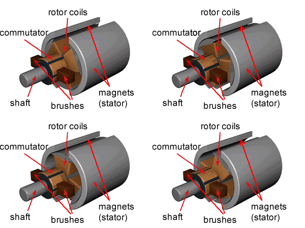
1 Always connect the two motor wires to M and M?. A DC series motor is used where speed regulation is not important dc series motor diagram and torque characteristics are shown in the above picture The main advantage of this dc series motor is that a high torque can be obtained, which makes it useful for applications such as diesel locomotives, cranes, etc. DC Motor Diagram Different Parts of a DC motor A DC motor is composed of the following main parts Armature or Rotor The armature of a DC motor is a cylinder of magnetic laminations that are insulated from one another The armature is perpendicular to the axis of the cylinder The armature is a rotating part that rotates on its axis and is.
We know that Dc Motor Magnetic lines of force travel from North pole to South pole The lines of force between these two poles in parallel. Here is a simple DC electric motor variable speed controller circuit that can be configured to control the sweep rate of automobiles’ windscreen wipers The circuit comprises a timer NE555 (IC1), mediumpower motor driver transistor BD239 (T1), highpower switching transistor BD249 (T2) and a few other discrete components. Theoretically, the same DC machine can be used as a motor or generator Therefore, construction of a DC motor is same as that of a DC generator Working principle of a DC motor An electric motor is an electrical machine which converts electrical energy into mechanical energy The basic working principle of a DC motor is "whenever a current carrying conductor is placed in a magnetic field, it.
Collection of dc motor wiring diagram 4 wire A wiring diagram is a streamlined conventional pictorial representation of an electrical circuit. Figure 3 – Diagrams of the various types of DC motor Parallel excitation (separate or shunt) The coils, armature and field coil are connected in parallel or supplied via two sources with different voltages in order to adapt to the characteristics of the machine (eg armature voltage 400 volts and field coil voltage 180 volts). Wiring a DC motor and Universal motor for speed control I use a vacuum motor, electric lawn mower, and Treadmill motors to demonstration some cheap options.
Theoretically, the same DC machine can be used as a motor or generator Therefore, construction of a DC motor is same as that of a DC generator Working principle of a DC motor An electric motor is an electrical machine which converts electrical energy into mechanical energy The basic working principle of a DC motor is "whenever a current carrying conductor is placed in a magnetic field, it. Assortment of ge single phase motor wiring diagram A wiring diagram is a streamlined standard pictorial depiction of an electrical circuit It shows the parts of the circuit as simplified forms, and also the power as well as signal links in between the devices. The Dc Motor Types & Dc Motor is a Mechanism by which Electrical Energy is Converted into Mechanical EnergyBoth in principle and in design, the DC motor is the reverse of a DC Generator Dc Motor Magnet?.
Simple model of a DC motor!. DC Motor Diagram Different Parts of a DC motor A DC motor is composed of the following main parts Armature or Rotor The armature of a DC motor is a cylinder of magnetic laminations that are insulated from one another The armature is perpendicular to the axis of the cylinder The armature is a rotating part that rotates on its axis and is. Armature Induced Voltage & Torque The armature induced voltage E a is proportional to the speed and armature current whereas the torque T a of series motor is directly proportional to the square of armature current & it is given by.
A Universal Electric Motor is designed to operate on either alternating current or direct current (AC/DC) It is a series wound motor It is provided with a field winding on the stator which is connected in series with a commutating winding on the rotor Commonly manufactured in fractional horsepower sizes. Forward reverse dc motor control diagram with timer ic dc motor clockwise anticlockwise control h bridge circuit rov joystick for props dc motor reversing circuit timer or remote control quasar No comments yet Leave a Reply Cancel reply Post navigation Level 1 Data Flow Diagram For Online Examination System. DC Motor Model In this example, you model a DC motor driven by a constant input signal that approximates a pulsewidth modulated signal and look at the current and rotational motion at the motor output To see the completed model, open the PWMControlled DC Motor example Select Blocks to Represent System Components.
R a is the armature resistance R se is the series field resistance;. Block Diagram and Transfer Function of DC Motor Armature Controlled DC Motor Consider the armature controlled dc motor and assume that the demagnetizing effect of armature reaction is neglected, magnetic circuit is assumed linear and field voltage is constant ie if=constant Let Ra=Armture resistance La=Armatureself inductancecausedbyarmatureflux ia=armaturecurrent if=fieldcurrent E. BLDC motor stator winder coil winding machine from brushless dc electric motor diagram , sourceyoutubecom DRV07 Brushless DC Motor Controller Rev A Three from brushless dc electric motor diagram , sourcefdocumentsin So, if you’d like to receive all these fantastic photos regarding (Brushless Dc Electric Motor Diagram.
In the circuit diagram shown, the switch S1 is ON and switch S2 is OFF So, the motor terminals will have a positive polarity on the left side and a negative polarity at the right side Thus, the motor turns in a clockwise direction Similarly, when the S2 is ON and S1 is OFF, the motor turns in an anticlockwise direction Motor modes of operation. A DC motor may have both field winding s wound on the same pole Shunt motor PowerFlow Diagram A DC motor is a machine which converts electrical ener gy (or power) into.
All About Shunt Dc Motors What They Are And How They Work
Don T Ignore The Humble Brushed Dc Motor Mouser

Dc Motors And Stepper Motors Used As Actuators

Dc Motor Speed Control Block Diagram Download Scientific Diagram

Schematic Views Of A Brushed Dc Motor In The Closed Circuit Applied As Download Scientific Diagram
Basics Of Ac Dc And Ec Electric Motors Part 1 Ac And Dc

Dc Motor How It Works Magnetic Innovations

Diagram 6 Pole Dc Motor Wiring Diagram Full Version Hd Quality Wiring Diagram Jrschematicsn Artemisiacontemporanea It

Control Tutorials For Matlab And Simulink Motor Speed System Modeling

The Dc Counter Emf Motor Controller And Dc Variable Speed Motor Drives

A Short Illustrated Primer On Brushed Dc Motors Precision Microdrives
Introduction To Dc Motor Basics For Beginners Electronics For You
Dc Motor Control Matlab Simulink Example

Dc Motors How Do They Work Construction Working Principle Of A Dc Motor Electrical4u Youtube
Simple 12v 9v 6v Motor Dc Speed Control With Pwm Mode

Transfer Function Block Diagram Of Armature Controlled D C Motor Youtube
How A Dc Motor Works Electricaleasy Com
Dc Motor

Induction Motor Dc Test For Stator Resistance And Locked Rotor Test The Engineering Knowledge
Circuit Diagram Of A Separately Excited Dc Motor Field And Armature Download Scientific Diagram

Dc Motors And Stepper Motors Used As Actuators

Dc Motor Speed Voltage And Torque Relationships Precision Microdrives
Modeling Dc Motor Ppt Download

Compound Wound Dc Motor Or Dc Compound Motor Electrical4u
A Draw A Neat And Labelled Diagram Of A D C Motor And Explain Its Construction And Working Sarthaks Econnect Largest Online Education Community

Dc Motors What Would Dennis Do

Dc Motor Dc Fan Speed Controller Circuit Fan Fan Speed Motor

How To Drive Dc Motor With Arduino Arduino Project Hub

Compound Wound Dc Motor Or Dc Compound Motor Electrical4u
All About Series Wound Dc Motors What They Are And How They Work

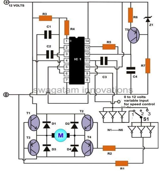
3 Simple Dc Motor Speed Controller Circuits Explained
Toy Hobby Dc Motor Pinout Wiring Specifications Uses Guide And Datasheet

Brushless Dc Motor Ac Motors Electronics Textbook

Dc Motors And Stepper Motors Used As Actuators

Diagram Of The Dc Shunt Motor Download Scientific Diagram
Dc Motor Wikipedia
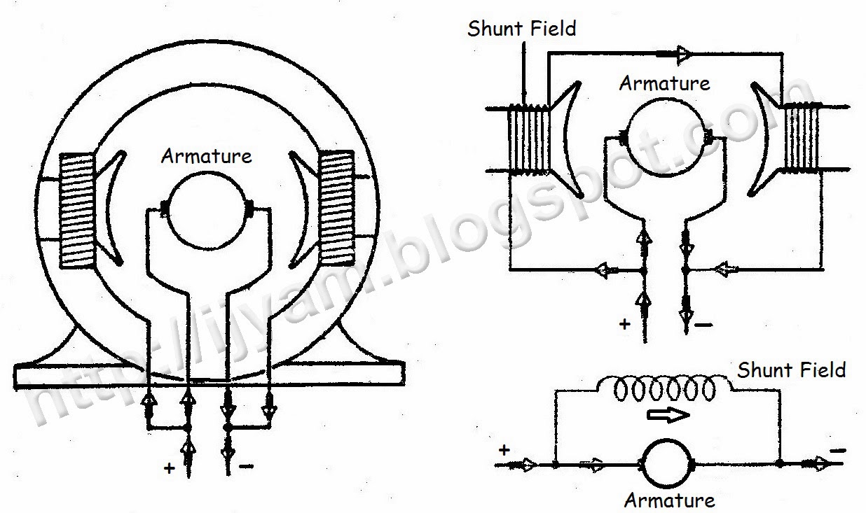
Diagram 6 Pole Dc Motor Wiring Diagram Full Version Hd Quality Wiring Diagram Jrschematicsn Artemisiacontemporanea It

12 Volts Dcmotor Speed Controller Circuit Diagram Electronics Basics Electronic Schematics
Electricity 3 Pole Dc Electric Motor

Dc Motor Or Direct Current Motor What Is It Diagram Included Electrical4u

Schematic Diagram Of Armature Controlled Dc Motor Notations R Download Scientific Diagram

Dc Motor Definition Examples Diagrams

Dc Shunt Motor Speed Control Characteristics Electrical4u
4 Types Of Dc Motors And Their Characteristics

Classifications Of Dc Machines Dc Motors And Dc Generators Electricaleasy Com
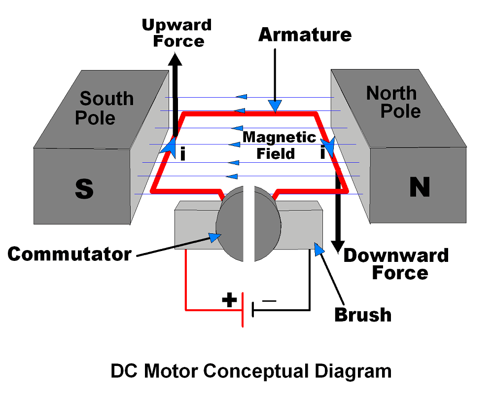
Diagram Bike Dc Motor Diagram Full Version Hd Quality Motor Diagram Haywiring Giornatedellaserra It

Dc Machine Fundamentals Dc Motor And Generator Dc Motor Construction Dc Motor Dc Generator Youtube

Connection Diagram Of Dc Compound Motor Application Wiring Diagram

Diagram 12v Dc Motor Diagram Full Version Hd Quality Motor Diagram Mkowiringn Innovationcircus It
Dc Motor Speed Modeling
3 Simple Dc Motor Speed Controller Circuits Explained
Dc Servo Motor
Www Egr Msu Edu Classes Me451 Jchoi 12 Notes Me451 L8 Pdf

Block Diagram Of An Armature Controlled Dc Motor Download Scientific Diagram
A Schematic Diagram Of Dc Motor And Accessories 13 B Simplified Download Scientific Diagram

Electrical Page Dc Motor Control Circuit Diagram Circuit Diagram Electrical Circuit Diagram Electrical Engineering

Circuit Diagram Of Dc Series Motor Dc Series Motor Circuit Diagram Circuit Diagram

Dc Shunt Motors Where Are They Used

12v 24v 10a Pwm Control Dimmer Of Speed For Dc Motor Electronics Projects Circuits
Simple 12v 9v 6v Motor Dc Speed Control With Pwm Mode
How To Build A High Torque Dc Motor Speed Controller Circuit Bright Hub Engineering
Types Of Dc Motor Shunt Series Compound Wound Motor Circuit Globe

Schematic Of The Dc Motor And Gear Box Download Scientific Diagram

How Can I Wire A Dc Motor If I Have The Motor Wiring Diagram
Q Tbn And9gcrdb16d70tfunj4lwsgf1hp Tk7z9hq2ejmnhhal4drm9s0jrh Usqp Cau

Eml2322l Electric Dc Motors

A Block Diagram Of The Dc Motor Download Scientific Diagram

Dc Shunt Motor Construction Circuit Diagram And Its Applications

Dc Motor Speed Control Using Microcontroller Pic 16f877a Microcontrollers Solar Projects

Electric Traction Control The Railway Technical Website Prc Rail Consulting Ltd

Dc Motor Or Direct Current Motor What Is It Diagram Included Electrical4u
Dc Electric Motors
Basics Of Brushless Dc Motors Bldc Motors Construction Working
Q Tbn And9gcre6y8jqwueh6aaevmelwpoj6eag Euotpxksa0jk1e 35yqzh4 Usqp Cau

Dc Series Motor Circuit Diagram Characteristics And Its Applications

Dc Motors The Process Technology And Operator Academy

Speed Control Of Dc Motor Dc Motor Speed Control Youtube

Construction Of Dc Motor Parts Images Electrical4u
Permanent Magnet Dc Motor Its Applications Advantages Disadvantages Circuit Globe
Types Of Dc Motor Steadt State Equivalent Circuit Moving Coil Motors
4 Types Of Dc Motors And Their Characteristics
Dc Motor Control Using Thyristor
Q Tbn And9gcq68cdryastml4eydvriob Wgxtvjdqwkdnvybvnrlcanifga1a Usqp Cau
Scr Dc Motor Speed Control Circuit Using Ic Cmos

Draw The Diagram Of A Dc Motor And Label The Parts
How To Build A Dc Motor Circuit
Dc Motor Speed Controller Detailed Circuit Diagram Available

Series Dc Motor Connections Youtube

Dc Motors And Stepper Motors Used As Actuators

Block Diagram Representation Of The Permanent Magnet Dc Motor Download Scientific Diagram

The Diagram Shows A Simple D C Electric Motor Which Is Rotating Which Change Makes The Motor Rotate More Quickly

Dc Motor Schematic Search Easyeda

Dc Motor Theory Worksheet Dc Electric Circuits

The Dc Counter Emf Motor Controller And Dc Variable Speed Motor Drives

Armature Controlled Dc Motor Wikipedia
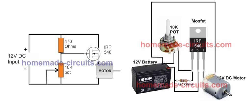
3 Simple Dc Motor Speed Controller Circuits Explained

Dc Motors Explained Advantages Of Brushed Brushless Motors Youtube


