Rf Signal Generator Circuit

Function Generators Manufacturer Supplier In India Scientech
Q Tbn And9gcrwsgf 2ovq8fquvwp17m4dionkamklwub0gzgj5ftakhbfpsil Usqp Cau

Zl2pd Simple Rf Signal Generator
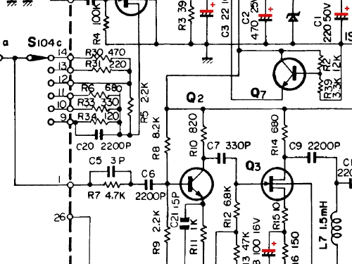
Rf Signal Generator 50 Equipment B K Precision Dynascan C

Figure 1 From Project1 5 8 Ghz Rf Signal Generator Semantic Scholar
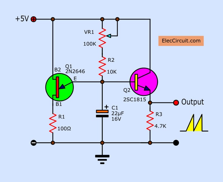
All Of Rf Radio Frequency Oscillator Fm Transmitters Circuits Projects
RF Power Amplifier Board Transmitter Circuit Board Amplifier Module dB Gain 50M6000Mhz SBB50 Application weak RF signal amplifier, RF power amplifier preamplifier 1 x RF Amplifier Board 35MHz4400MHz RF Signal Generator ADF4351 Module Sweep Frequency Generator PLL W $2999 Free shipping Popular.
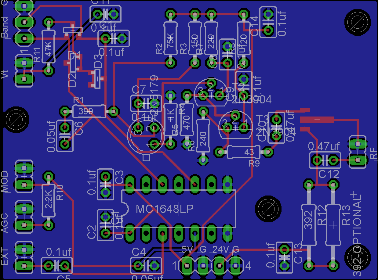
Rf signal generator circuit. The generators also contain a keying circuit which allows the generators to be keyed on and off with a TTL logic signal, and the rise time of the rf can be adjusted In many applications, this keying circuit is not required and the generator is simply operated in CW mode In this case, the keying circuit can be omitted. Radio frequency, RF signal generators are an essential item of test instrumentation for any area where RF or microwave test and development is undertaken A microwave or RF signal generator provides a signal source that can be used to test the operation of the circuit being tested or developed. Sensor Circuits (16) Signal Conditioners (11) Signal Generators (13) Speed Controller Circuits (1) State space analysis (2) Switching Circuits (6) Tech News () Telephone Related (9) Television Related (4) Temperature Related (3) Test & Measurement Circuits (38) Testing Components (9) Three phase circuits (1) Timer Circuits (3) Tone generator.
Handy RF signal source Because the signal generator is rich in harmonics, it makes a cheap and handy RF signal source You do not have to tune a signal generator to get a signal near the tuning range of your receiver Receiver adjustment for peak input response One of the first things you usually do after completing a receiver project is the. The RF signal generator is a must to have tool when playing with radio receivers It is used to tune a resonant circuits and adjust the gain of different RF stages Very useful feature of the RF Signal generator is its modulation capability If it can modulate the frequency amplitude or frequency makes it non replaceable tool for RF design works. About DIY RF Sweep Generator The resource is currently listed in dxzonecom in a single category The main category is RF Sweep Generatos projects that is about Projects for RF sweep generators This link is listed in our web site directory since Saturday Apr 4 15, and till today "DIY RF Sweep Generator" has been followed for a total of 1300 times.
A Function generator, often known as Waveform generator is a circuit that produces a variety of different waveforms at a desired frequency Function generator is one of the important devices in laboratory when it comes to generating electrical waveforms like sine, triangle,square or pulses over a range of frequencies, amplitude and duty cyle. RF Signal Generator DDS Arduino Shield AD9910 600MHz And only after that it was possible to turn on this whole circuit and measure the output signal It is better to do all this with a spectrum analyzer we used a receiver based on the IC MC3362, and fed the RF signal from the DDS AD9910 to the heterodyne input of the MC3362, and the. The design is based on two lCs only, and uses readymade inductors in the frequency determining sections.
To receive the signal, we used a receiver based on the IC MC3362, and fed the RF signal from the DDS AD9910 to the heterodyne input of the MC3362, and the Yaesu VX6R radio station was used as a transmitter But despite the highquality transmitter, we could not hear anything except noise and screeching. RF Signal Generators (Signal Sources) Delivers all the reliability and capabilities you expect from Keysight at the lowest possible price Assure quality while minimizing the cost of your general purpose testing with reliable RF performance and capability. Full support for vector signal modulation on RF carriers between 400 MHz and 6075 GHz It features a dual, arbitrary waveform generator operating at 125 MHz for baseband signal generation The generator has builtin support for the most common vector modulation schemes ASK, QPSK, DQPSK, π/4 DQPSK, 8PSK, FSK, CPM QAM (4 to 256), 8VSB, and 16VSB.
The AF and RF signal generator can used as the source test signal for an Antenna analyser project, signal amplification may be required for the antenna balance measurements detection circuit, the measurement of the unknown impedance of the antenna under test Below is a list of the data connection ports of D0 D13, and analog ports A0 A5. The Signal Tracer RF and audio probe using Lm386 integrated circuit is geared towards maintaining preamplifier, power amplifiers and even RF devices As a probe of audio signal and RF, can make maintenance of equipment such as amplifiers, preamplifier, radios, car audio, transmitters, recorders, televisions and more. Troubleshooting an RF stage is fairly straight forward generator, a modulated signal is applied to the antenna terminals and if the stage is working properly, the amplified signal will appear in the plate circuit, across the interstage transformer T2, to be passed on the converter.
ERASynth Micro is a USBPowered, Low Priced, Open Source RF Signal Generator, by ERA Instruments ERASynth Micro is an open source signal generator with impressive features Everyone can afford it, including makers, hackers, students, ham radio and SDR users. Troubleshooting an RF stage is fairly straight forward generator, a modulated signal is applied to the antenna terminals and if the stage is working properly, the amplified signal will appear in the plate circuit, across the interstage transformer T2, to be passed on the converter. IC1d is a comparator that monitors the total Vt voltage applied to the RF generator varactor This monitors the Vt output stage in the generator Its trip point is set to the maximum voltage that the varactor was designed to handle That voltage may be pure DC, Ramp AC peak, or the combination of both.
RF signal generator This is used as the signal source to drive the impedance bridge and detectors used to measure impedance Those instruments ended up with somewhat different oscillator designs due to other conflicting design issues The signal generator outlined. KKmoon RF Signal Generator, 05MHz470MHz RF Signal Generator Meter Tester for FM Radio WalkieTalkie Debug Digital CTCSS Singal Output 27 out of 5 stars 7 $ $ 101 99. RF Signal Generator DDS Arduino Shield AD9910 600MHz The way to create a highprecision generator from 100 kHz to 600 MHz based on DDS from Analog Devices AD9910 Intermediate Showcase (no instructions) 5,404 Things used in this project.
Simple signal tracer is ideal for tracing RF and audio signals in radio receivers and audio amplifiers by Rick Walters Build An Audio/RF Signal Tracer June 1997 Outer Front Cover. Since the tank circuit coils on the RF deck have 16 VDC of bias voltage on them, we need an RF ground on their low side which has to be isolated from DC This is accomplished by cutting a piece of singlesided circuit board to the approximate shape of the switch wafer. The signal generator is exactly what its name implies a gener ator of signals used as a stimulus for electronic measurements Most circuits require some type of input signal whose amplitude varies over time.
Many of the better ones can generate up to 30 MHz Function Generators are not as stable or low noise as an RF signal generator, and often the RF signal generator has a better variable attenuator For an RF signal generator, consider something like this GW Instek RF Signal Generator GRG450B NICE eBay. It covers a radio frequency range of 85 kc/s to 25 Mc/s and gives a continuously variable output of one microvolt to one volt This is controlled by a calibrated attenuator and may as required be modulated either externally, or by the internal 400 c/s oscillator. RIGOL Technologies recently expanded its portfolio of RF Test solutions with the launch of the DSG800 Series RF Signal Generator The series—which is targeted at engineers implementing Bluetooth, WiFi, and other RF interfaces in embedded systems—covers output frequencies from 9 kHz to 3 GHz It provides maximum output power up to dBm and low SSB phase.
The Radio Frequency or RF signal generators are the vital electrical instrument that produces electronic signals with a certain set of properties including frequency, amplitude, and wave shape They are an essential item to test instruments at any place where radio frequency or development work is being done Precisely, it’s a source of the signal that can be used to test the circuit that is. SWEEP FREQUENCY GENERATOR Like an oscillator, a signal generator is also a source of sinusoidal signals The main difference between a signal generator and an oscillator is that a signal generator is capable of modulating its sinusoidal output signal with other signals. SWEEP FREQUENCY GENERATOR Like an oscillator, a signal generator is also a source of sinusoidal signals The main difference between a signal generator and an oscillator is that a signal generator is capable of modulating its sinusoidal output signal with other signals.
Signal Generators Circuits and Tutorials 1KHz Sine Wave Generator, 3 to 12 MHz Signal Generator, Low Cost Function Generator Circuit, Musical Tone Generator, RF Signal Generator, Signal Generator for Signal Tracer, Sine Wave Generator With Crystal Accuracy, Triangle Waveform Generator. RF Signal Generator The RF signal generator is a must to have tool when playing with radio receivers It is used to tune a resonant circuits and adjust the gain of different RF stages Very useful feature of the RF Signal generator is its modulation capability. Sensor Circuits (16) Signal Conditioners (11) Signal Generators (13) Speed Controller Circuits (1) State space analysis (2) Switching Circuits (6) Tech News () Telephone Related (9) Television Related (4) Temperature Related (3) Test & Measurement Circuits (38) Testing Components (9) Three phase circuits (1) Timer Circuits (3) Tone generator.
At the generator output, across a range of –1 dB through –79 dB An optional serial interface is available to enable the RF Signal Generator to be linked to a PC using an RS232 cable Functionally, the instrument is completed by an internal power supply PLL BOARD The circuit diagram of this first module to be discussed in detail is shown. The Signal Tracer RF and audio probe using Lm386 integrated circuit is geared towards maintaining preamplifier, power amplifiers and even RF devices As a probe of audio signal and RF, can make maintenance of equipment such as amplifiers, preamplifier, radios, car audio, transmitters, recorders, televisions and more. This is a Simple IF AM signal generator circuit with, 455kHz output frequency We use simple components, CMOS IC CD4011, CD4040 And control fixed frequency using the crystal3579 MHz In the event of AM radio repairs The basic tools that are usually found the IF signal frequency generator We will use it to determine the function of various.
Hi welcome to my design for a simple (and cheap) RF signal generator with both AM and FM modulation The version I built was to fill in the gaps not covered by my old commercial unit and also provide an item of test equipment in its own right As built the frequency range mine covered was 16KHz to 54 MHz although with suitable coils it should. This is simple signal injector circuit, used two transistors join together as astable multivibrator, signal output frequency 1,000Hz in square waveform And the second circuit is 1KHz Signal injector for electronic technicians. It covers a radio frequency range of 85 kc/s to 25 Mc/s and gives a continuously variable output of one microvolt to one volt This is controlled by a calibrated attenuator and may as required be modulated either externally, or by the internal 400 c/s oscillator.
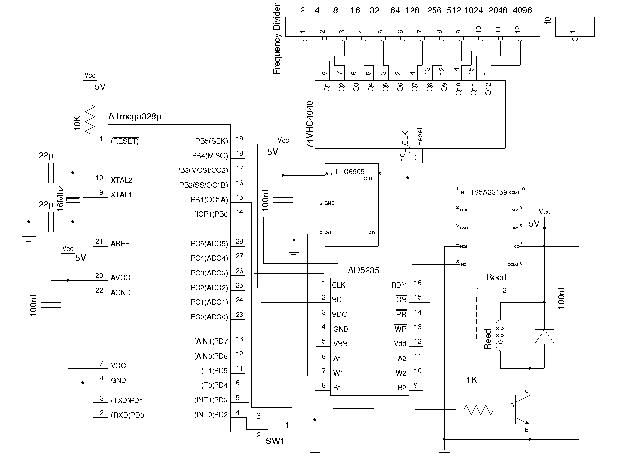
CW Signal Generator Looking at a basic block diagram of theCW signal generator, the RF CW source splits into three sections reference, synthesizer, and output (Fig 2) Thereference section. Introduction A simple looking RF signal jammer circuit can be seen in the above diagram, which may be capable of jamming all sorts RF signal within the range of 5 to 10 meters The circuit can be made suitable with any desired frequency to be jammed by merely using different sets of L1/L2 and by tweaking the 22pF trimmers accordingly. The following is the circuit diagram for this wide band signal generator 4KHz to 170MHz Signal Generator Schematic The frequency of the LTC6905 output is determined by the divider (pin 4) setting along with the voltage applied on pin 3.
RF Signal Generator DDS Arduino Shield AD9910 600MHz The way to create a highprecision generator from 100 kHz to 600 MHz based on DDS from Analog Devices AD9910 Intermediate Showcase (no instructions) 5,404 Things used in this project. Signal Generator Block Diagram The signal generator block diagram is shown below In the block diagram, voltage controlled oscillator is an essential part because the input controlled voltage can be determined through the frequency of the voltagecontrolled oscillator So both the control voltage and VCO’s frequency are directly proportional. Written by Circuit Cellar Staff RIGOL Technologies recently expanded its portfolio of RF Test solutions with the launch of the DSG800 Series RF Signal Generator The series—which is targeted at engineers implementing Bluetooth, WiFi, and other RF interfaces in embedded systems—covers output frequencies from 9 kHz to 3 GHz.
The signal generator is exactly what its name implies a gener ator of signals used as a stimulus for electronic measurements Most circuits require some type of input signal whose amplitude varies over time. How Does the Signal Generator Work?. To receive the signal, we used a receiver based on the IC MC3362, and fed the RF signal from the DDS AD9910 to the heterodyne input of the MC3362, and the Yaesu VX6R radio station was used as a transmitter But despite the highquality transmitter, we could not hear anything except noise and screeching.
Depending on the RF Explorer model you have, you may need to order a separate top aluminum CNC cover Please check this product from SeeedStudio for more details Adding an Expansion Module to RF Explorer Signal Generator is an easy but delicate task, please follow the process with care to details to make sure everything works fine after the. A Function generator, often known as Waveform generator is a circuit that produces a variety of different waveforms at a desired frequency Function generator is one of the important devices in laboratory when it comes to generating electrical waveforms like sine, triangle,square or pulses over a range of frequencies, amplitude and duty cyle. Introduction A simple looking RF signal jammer circuit can be seen in the above diagram, which may be capable of jamming all sorts RF signal within the range of 5 to 10 meters The circuit can be made suitable with any desired frequency to be jammed by merely using different sets of L1/L2 and by tweaking the 22pF trimmers accordingly.
Working of the circuit is straightforward when the two O1 germanium diodes get an RF signal thus they convert it into DC signal This DC signal is additionally enhanced by the NPN transistor 2N4401 and sends it to the base of the 2N4403 PNP transistor consequently doing it switch ON and enact the bell or buzzer. The bestknown tuneable solidstate RF signal generator is the HP 8640Bseries The 8640B has been a real workhorse over the years;. Working of the circuit is straightforward when the two O1 germanium diodes get an RF signal thus they convert it into DC signal This DC signal is additionally enhanced by the NPN transistor 2N4401 and sends it to the base of the 2N4403 PNP transistor consequently doing it switch ON and enact the bell or buzzer.
Three new RF Signal Generators, with carrier frequencies from DC to 25 GHz, 4050 GHz and 6075 GHz, support both analog and vector modulation The instruments utilize a new RF synthesis technique which provides spur free outputs with low phase noise (–116 d/Hz at 1 GHz) and extraordinary frequency resolution (1 µHz at any frequency). The picture below shows the layout of the signal generator Because of the high frequencies it is operating under, I chose to enclose the whole circuit inside an aluminum case to reduce possible RF interference and thus makes the circuit more stable Frequency Generator 2 The Arduino code can be downloaded here FreqGenzip In my next post, I. N9310A RF signal generators cover a frequency range from 9 kHz to 3 GHz With a low price, reliable performance, and multiple builtin functions, they are general purpose instruments, ideal for R&D, manufacturing, education, and service maintenance.
The author’s RF generator used multiple transformers to deliver a variety of voltages The case I had was a little bit small, and I decided I’d try to redesign the circuit to use only a single centertapped 24 VAC transformer The first change I made was to use a common cathode varactor diode instead of a common anode varactor diode. The AF and RF signal generator can used as the source test signal for an Antenna analyser project, signal amplification may be required for the antenna balance measurements detection circuit, the measurement of the unknown impedance of the antenna under test Below is a list of the data connection ports of D0 D13, and analog ports A0 A5. Typical RF Signal Generator from 60's Slightly modified (on transistors) in production today Simplicity Just love simple schematic 3118 Simplest RF transmitter circuit (27MHz, AM) for RC toy This simple and reliable RF transmitter has two charms In the first of all, all unnecessary parts was removed.
Signal Generators Vaunix LSG and LMS Series Lab Brick RF and Microwave USB Programmable Digital Signal Generators offer high output levels and excellent spectral purity through 40 GHz They can be operated in both continuouswave (CW) and sweptfrequency modes. Signal Generator Block Diagram The signal generator block diagram is shown below In the block diagram, voltage controlled oscillator is an essential part because the input controlled voltage can be determined through the frequency of the voltagecontrolled oscillator So both the control voltage and VCO’s frequency are directly proportional. The output signal is developed across R6, and passes to the output sockets via variable and switched attenuater circuits The signal is amplitude modulated by varying the supply voltage to the oscillator circuit This is carried out by TR3, which is an emitter follower C10 decouples the feed at RF.
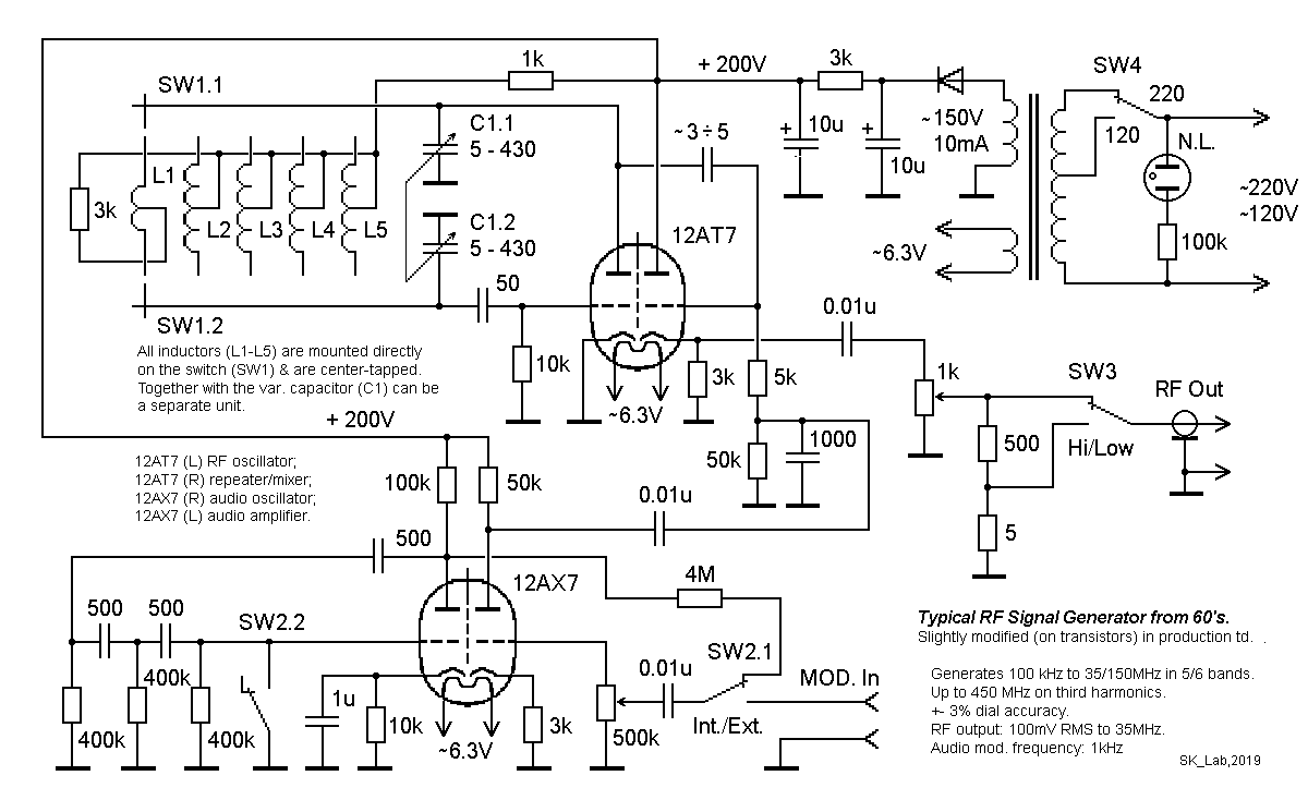
Typical Rf Signal Generator
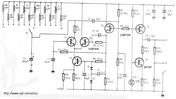
Rf Circuits Circuitos De Rf Littlesoft Electronics

Ideas About Rf Generator Block Diagram
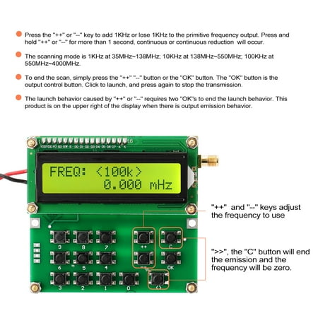
35mhz 4000mhz Rf Signal Generator Signal Source Adf4351 Vfo Hxy D6 V1 02 Specification Green Walmart Canada

Dubrow Ts 452 C U Sweep Signal Generator Oscilloscope Richard Sears Vintage Electronics
1
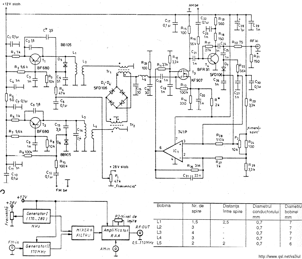
Rf Signal Generators And Multiplexers Generadores Y Multiplexores Littlesoft Electronics
Simple Rf Signal Generator Elektor Magazine

13cm Signal Generator

High Frequency Generator Circuit
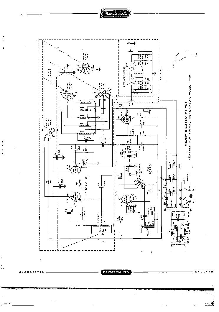
Heathkit Rf 1u Rf Signal Generator Sch Service Manual Download Schematics Eeprom Repair Info For Electronics Experts

The Difference Between Arbitrary Function Generators And Arbitrary Waveform Generators

China Su3630 3ghz Synthesized Rf Signal Generator With Usb And Rs 232 China Generators Signal Generator
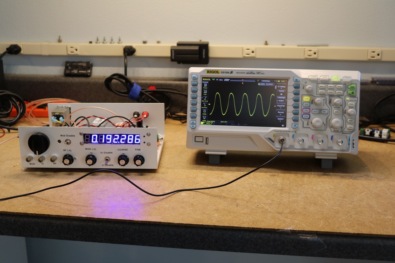
Diy Rf Signal Generator Dr Scott M Baker

Uk Vintage Radio Repair And Restoration Rf Signal Generator Vintage Radio Circuit Diagram Electronics Basics
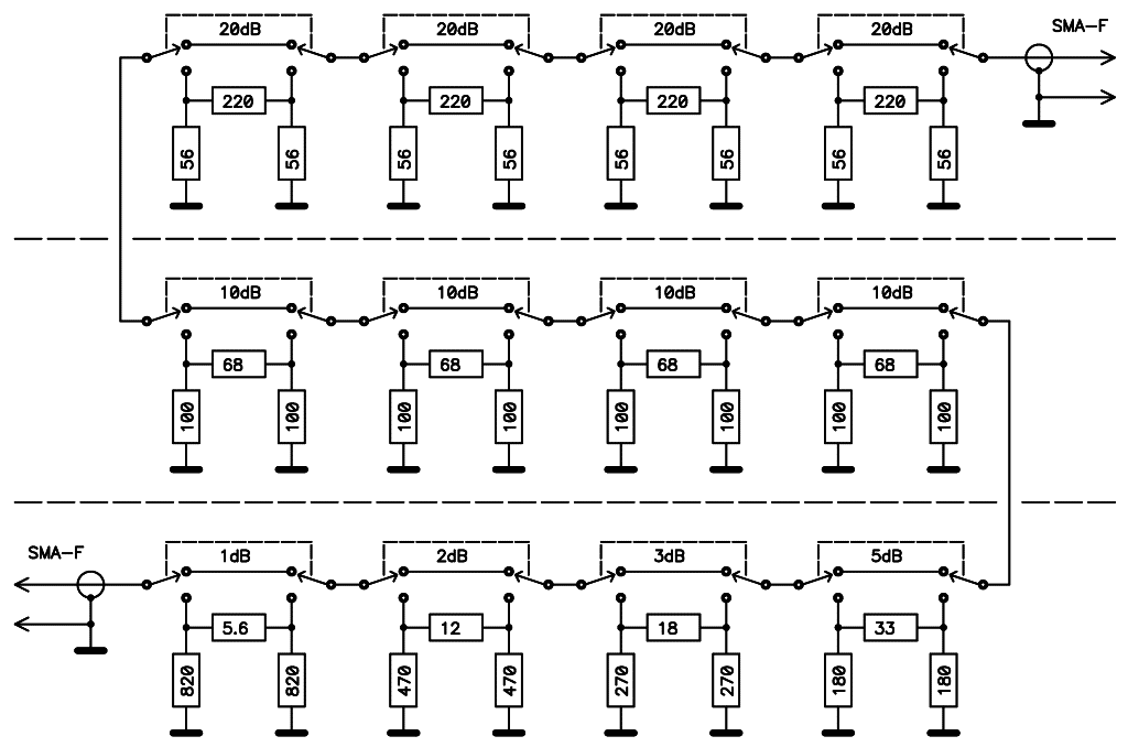
S53mv Dds Rf Signal Generator
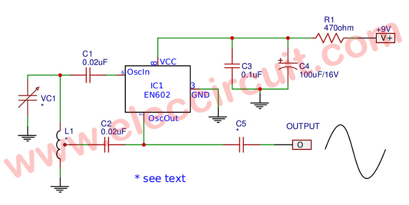
All Of Rf Radio Frequency Oscillator Fm Transmitters Circuits Projects
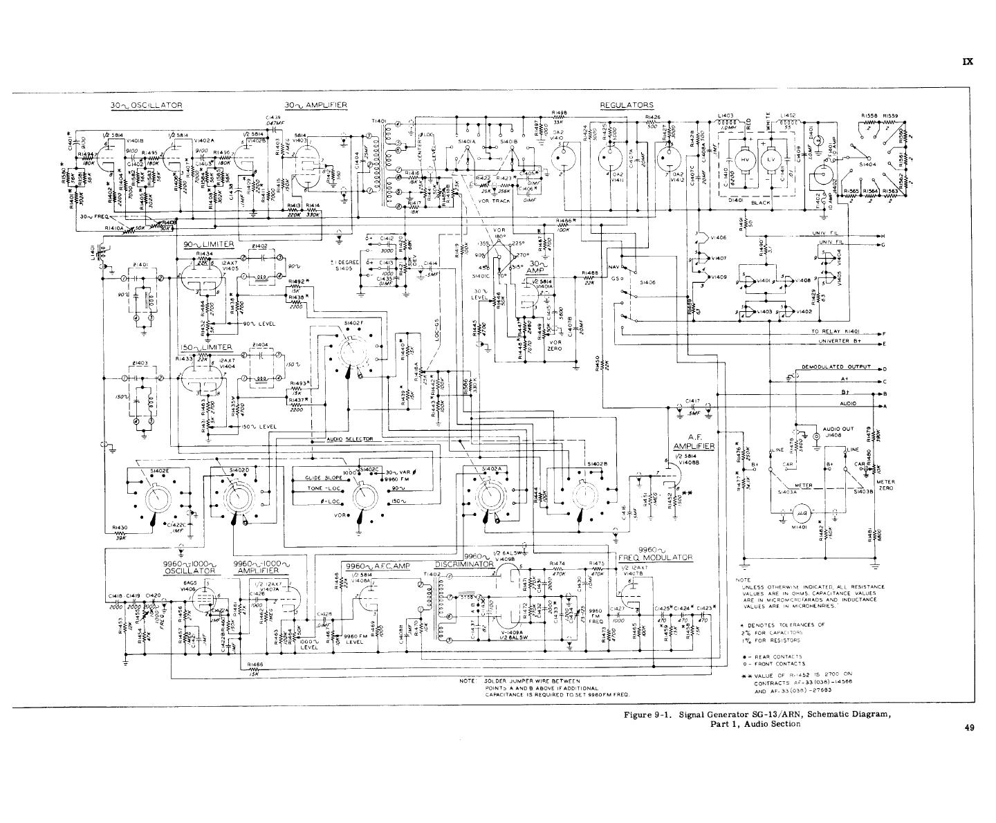
Figure 9 1 Signal Generator Sg 13 Arn Schematic Diagram Part 1 Audio Selection

Rf Signal Generator आरएफ स ग नल जनर टर In Adil Nagar Lucknow Turbo Scientific Id
Alan Yates Laboratory Rf Sweep Generator

The Difference Between Arbitrary Function Generators And Arbitrary Waveform Generators

Diy Rf Signal Generator Dr Scott M Baker

Cn0340 Circuit Note Analog Devices

Signal Generators Audio Through Rf Analog Devices
Analytics For Us Patent No Electrosurgical Generator Apparatus

Rf Signal Generator 8 Steps With Pictures Instructables
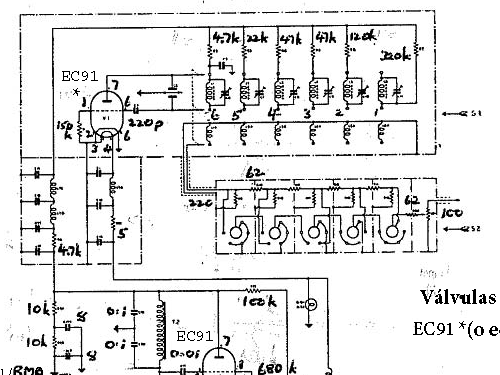
Af Rf Signal Generator 67a Equipment Taylor Electrical

35m 4 4g Rf Signal Generator Source Spot Pll Sweep Frequency Generator Usb Touch Ebay

Rf Signal Generator Msg703 Msg703 As Vector Signal Generator Micronix
All Waves Rf Generator Built And Modified By Sv3ora An Rf Signal Generator Is A Special Piece Of Test Equipment Which Allows You To Test A Wide Variety Of Rf Circuits And Perform Many Other Interesting Rf Experiments For Quite A Few Years I Was Trying To
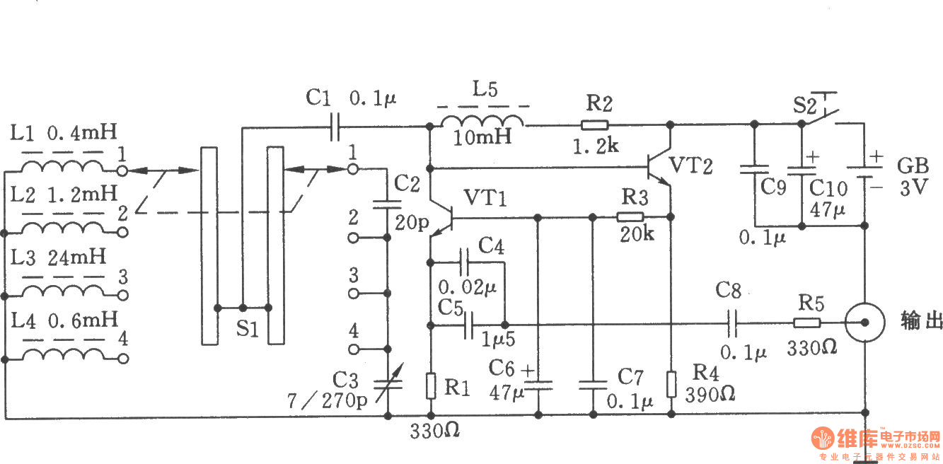
Simple High Frequency Signal Generator High Frequency Signal Generating Signal Processing Circuit Diagram Seekic Com
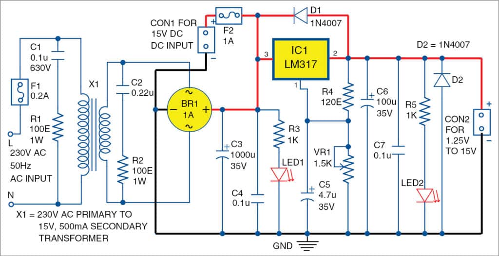
Signal Generator And Inverter Using Ne555 Timers Full Diy Projects
4khz 170mhz Wide Band Rf Signal Generator I Kerry D Wong
Rf Signal Generator Circuit Digest

Rf Signal Generator Dds Arduino Shield Ad9910 600mhz Arduino Project Hub
1

Signal Generator What Are They Circuit Block Diagram Electrical4u

Signal Generator Wikipedia
Tida 9 8ghz Rf Cw Signal Generator Using Integrated Synthesizer With Spur Reduction Reference Design Ti Com

Signal Generator What Are They Circuit Block Diagram Electrical4u
Simple High Frequency Signal Generator Circuit Diagram Under Oscillator Circuits Next Gr
05 Rf Signal Generator Circuitlab

Radio Frequency Rf Signal Generator Market Growth Report 17 By Ra

Zl2pd Simple Rf Signal Generator

Diy Rf Signal Generator Youtube
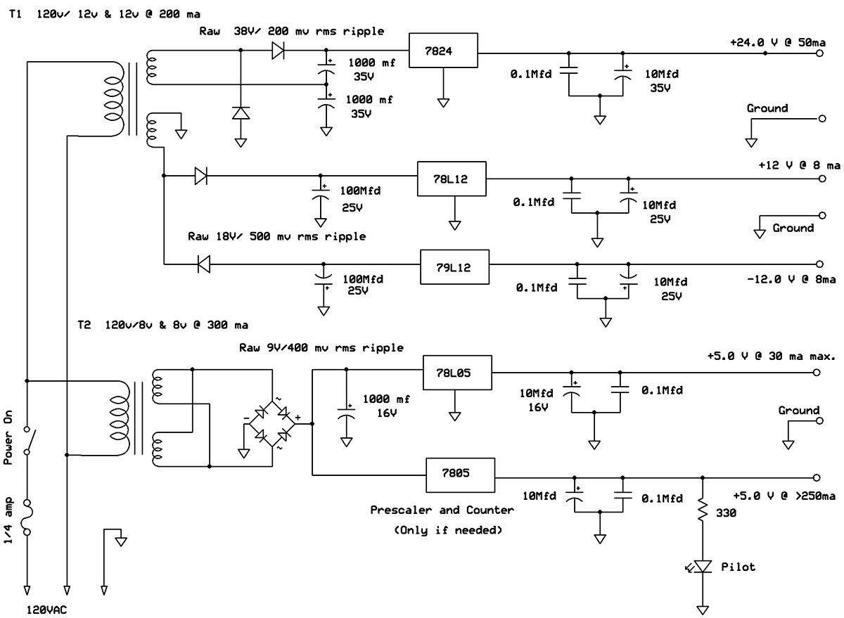
A 150 Mhz Rf Signal Generator For Your Test Bench Nuts Volts Magazine

Dave S Homemade Radios Visitors Page Nick S Rg Signal Generator
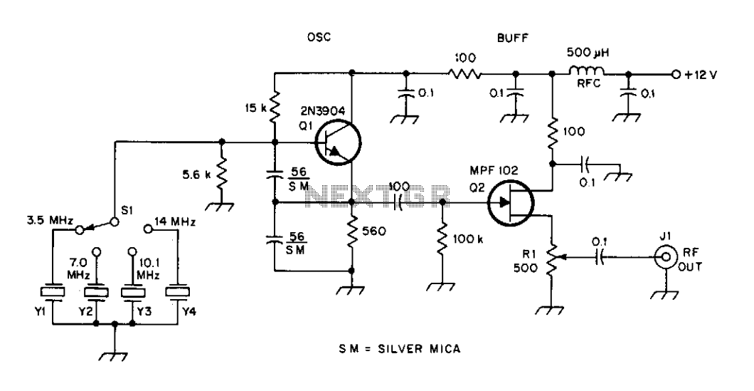
High Frequency Signal Generator Under Colpitts Oscillator Circuits Next Gr

Rf Signal Generator 8 Steps With Pictures Instructables

Schematic Of The Measurement Setup With Rf Set Electrometer Operated In Download Scientific Diagram

Rf Signal Generator Electronic Schematics Generation Electronics Basics
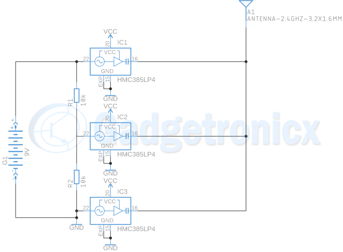
Generator Archives Gadgetronicx

Radio Frequency Heating Medium Guduru Rakesh Intrepid Brands Llc
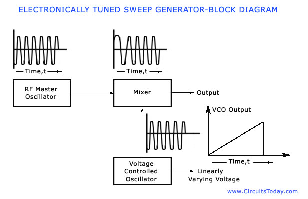
Sweep Frequency Generator Working Block Diagram Parameters Applications
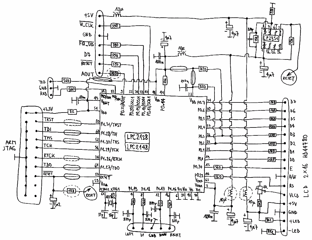
S53mv Dds Rf Signal Generator
3

Signal Generators Circuits Electronics Tutorial And Schematics Discover Engineering Hobby Projects

Rf Signal Generator Edn

Simple Rf Generator Yo4hhp S Blog
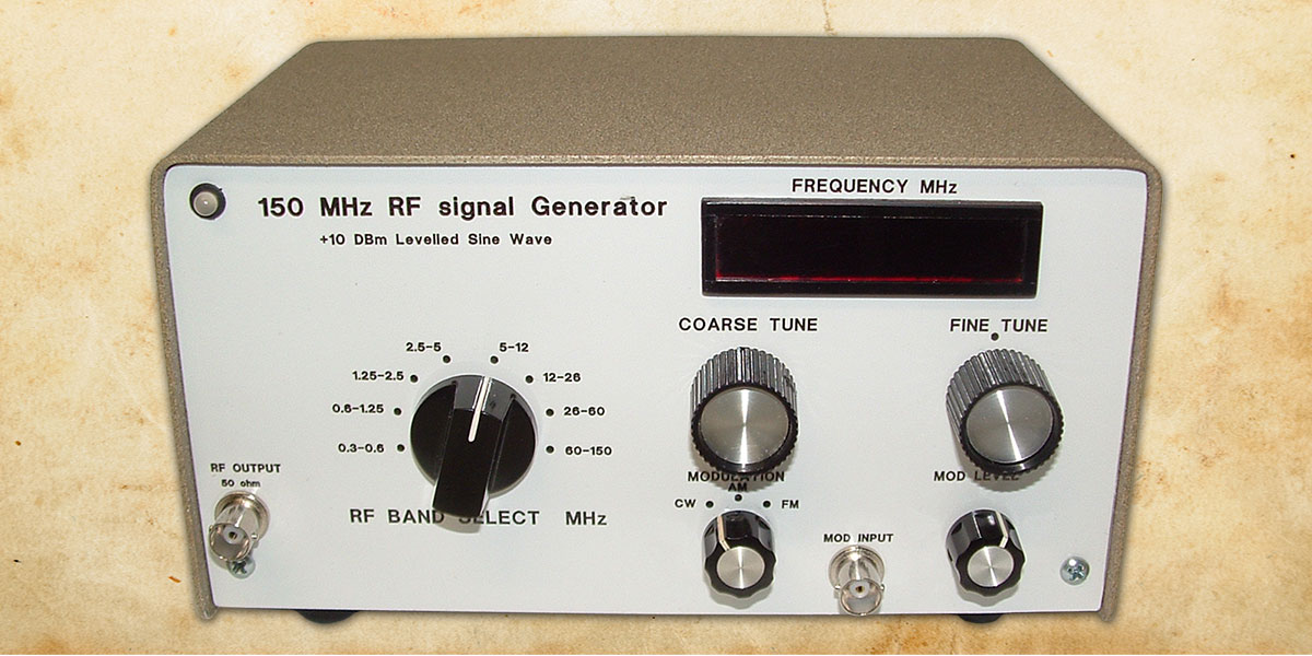
A 150 Mhz Rf Signal Generator For Your Test Bench Nuts Volts Magazine

Rf Signal Generator Project Part 1 Berk Omuz Personal Blog
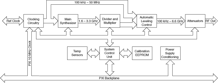
Ni Rf Signal Generator Hardware Operation Ni Rf Signal Generator Documentation

Rf Signal Generator Electronic Schematics Generation Electronics Basics
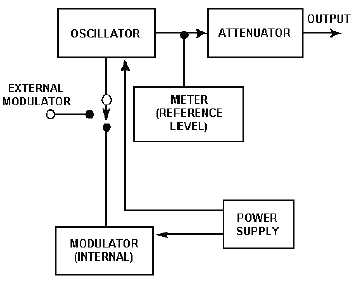
Radio Frequency Rf Signal Generators

3rdz0yjjlsmddm
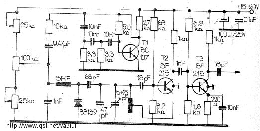
Rf Circuits Circuitos De Rf Littlesoft Electronics

Eico Rf Signal Generator Model 324

Figure 10 From Rf Cmos Integrated Circuit History Current Status And Future Prospects Semantic Scholar

Hg1462 Signal Generator Circuit Pdf Signal Generator Symbol Signal Generator Www Mcp Sh Com

Eevblog 3 Rigol Dsg815 Rf Signal Generator Teardown Youtube

Hp1 Rf Signal Generator 140mhz 4 4ghz Radio Frequency Signal Generator With Sweep Function Signal Generators Aliexpress

Pin On Technology
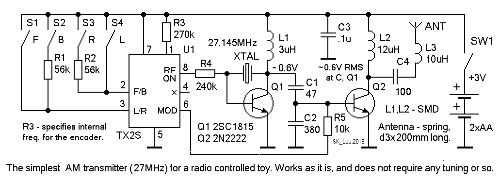
Typical Rf Signal Generator

Dave S Signal Generator To Regen Radio Conversion Using An Eico 315
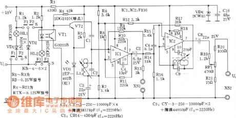
Index 130 Signal Processing Circuit Diagram Seekic Com
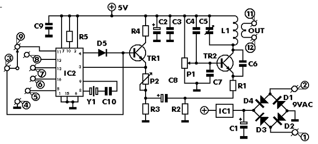
Radiosparks Schematics 1 21

Rf Signal Generator Circuit With 2n5458 Diy Electronics Projects Circuits Diagrams Hacks Mods Gadgets Gizmos

How To Make A Low Cost Rf Signal Generator

Wave Generator Circuit Download Scientific Diagram

Heathkit Rf 1u Signal Generator Service Manual Download Schematics Eeprom Repair Info For Electronics Experts

Adf4351 35m 4 Rf Signal Generator Pll Sweep Frequency Generator Press Screen 5v Buy Online At Best Prices In Bangladesh Daraz Com

All Waves Rf Generator Built And Modified By Sv3ora An Rf Signal Generator Is A Special Piece Of Test Equipment Which Allows You To Test A Wide Variety Of Rf Circuits And Perform Many Other Interesting Rf Experiments For Quite A Few Years I Was Trying To
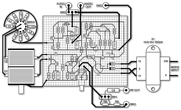
Uk Vintage Radio Repair And Restoration Rf Signal Generator

Nombrex Rf Signal Generator Model 27
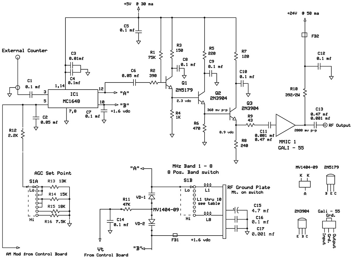
A 150 Mhz Rf Signal Generator For Your Test Bench Nuts Volts Magazine

Uk Vintage Radio Repair And Restoration Rf Signal Generator
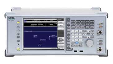
Rf Radio Frequency Signal Generator Electronics Notes

3 Alc

Amazon Com Rf Signal Source Module Generator High Speed Bistable Circuit For The Ac Way Of The Device Under Test Electronics
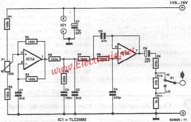
Sinusoidal Signal Generator Circuit Electronic Projects Power Supply Circuits Circuit Diagram Symbols Audio Amplifier Circuit Pdf Engineering Projects

Adf4351 35mhz 4 4ghz Pll Rf Signal Source Frequency Synthesizer Board Pmd Way
Gotronik Pl Images Tsg 17 Pdf

Field Effect Transistor Fet Projects Rf Signal Generator

Rf Signal Generator

Rf Signal Generator 8 Steps With Pictures Instructables
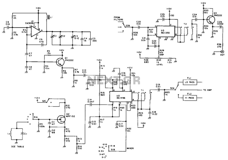
Rf Signal Generator Circuit Under Rf Oscillator Circuits Next Gr
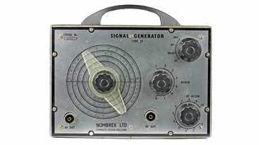
Rf Radio Frequency Signal Generator Electronics Notes
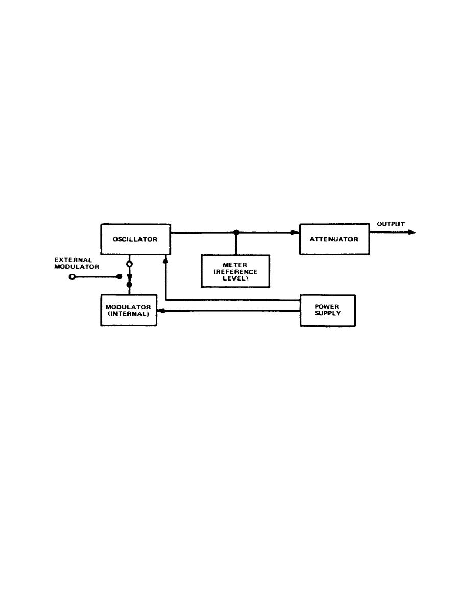
Figure 3 3 Block Diagram Of Rf Signal Generator


