Hplc System Diagram

Modeling High Performance Liquid Chromatography Comsol Blog
High Performance Pressure Liquid Chromatography Hplc Ppt Video Online Download
Q Tbn And9gctnlamy2rcwykvvlk6zpcmunaf0n2z4evsf Bvuytozo8inusnv Usqp Cau
High Pressure Liquid Chromatography Hplc Ibsen Photonics
Hplc

1 Principle And System Configuration Of Hplc 1 Hitachi High Tech Global
Myosmine were prepared and quantified using high performance liquid chromatography (HPLC) Various elution schemes were tested and adjusted for optimal analyte resolution, and a final elution scheme was developed to characterize ecigarette alkaloids.

Hplc system diagram. Computerbased system that controls all parameters of HPLC instrument (eluent composition (mixing of different solvents);. The detector measures the concentration of sample bands as they leave the column and pass through the detector flow cell When no band is passing through the detector, a constant signal is recorded called the Baseline of the chromatogram or detector When a sample band reaches the detector, the detector responds to the difference in the mobile phase properties caused by the presence of the. He used chalk in a glass column.
Demonstration of HPLC Instrument and Software Operation Perform Single Analysis 3 Instrument Specification 4 Shimadzu Model LCA System Pump(A & B) 2 LC10AT Detector SPDA Colum Oven CTOA Colum Shimpack VPODS(150mm x 46mm id 5µm ) Controller CBMAlite Software LCSOLUTION. USIng onLIne hPLC Figure 1 is a diagram of how the product purity data from the online HPLC is transmitted to the Distributed Control System (DCS), where it is compared to the product purity setpoints From these data the DCS will determine when to start and stop the collection of the product based. EN UHPLC System Operation Manual This manual provides instructions for installation, setup, startup, shutdown, operation, maintenance, and troubleshooting of the Thermo Scientific Vanquish Horizon UHPLC system and the Thermo Scientific Vanquish Flex UHPLC systems.
System Configuration System Configuration Manual isocratic HPLC System G1380AA standard configuration • G1310A isocratic pump with solvent cabinet • G1328A manual injector (MI) • G1314A variable wavelength detector (VWD) with standard flow cell (10 mm path length, 14 µl volume, 40 bar maximum pressure) • G22AA 2DValue Solution. The only purpose for this part of the system is to protect the analytical column from contamination, removes any potentially high absorbing compounds It can be discarded and replaced if contaminated Replacing this also decreases the pressure in the system. USIng onLIne hPLC Figure 1 is a diagram of how the product purity data from the online HPLC is transmitted to the Distributed Control System (DCS), where it is compared to the product purity setpoints From these data the DCS will determine when to start and stop the collection of the product based.
Crawford Scientific wwwchromacademycom 5 Where 1 Ion source The HPLC eluent is sprayed into the atmospheric pressure region 2 Skimmer Cone A cone with a sampling orifice of reduced diameter to preferentially sample gas phase ions and reduce the gas load entering the vacuum system of the mass. Note It is important to read the introductory page about thin layer chromatography before you continue with this one particularly the part about how thin layer chromatography works High performance liquid chromatography works on the same basic principle HPLC is essentially an adaptation of column chromatography so it might be a good idea to have a (very quick) look at that as well. HPLC is the most widely used type of chromatography;.
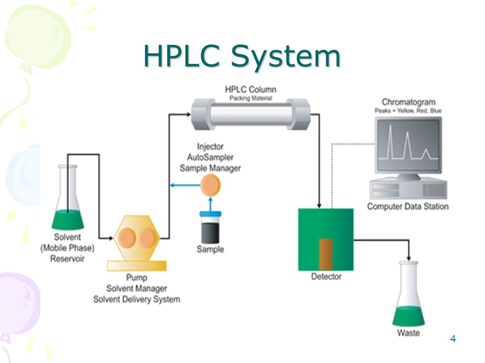
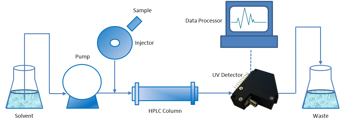
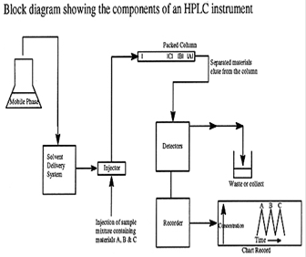
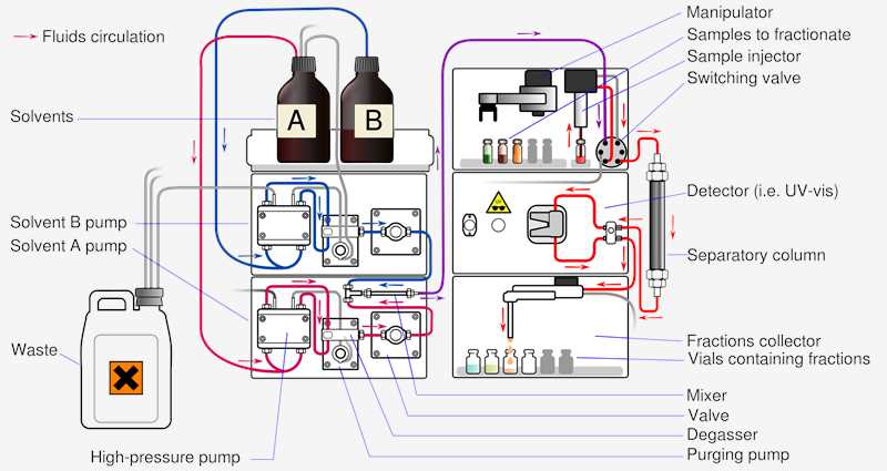
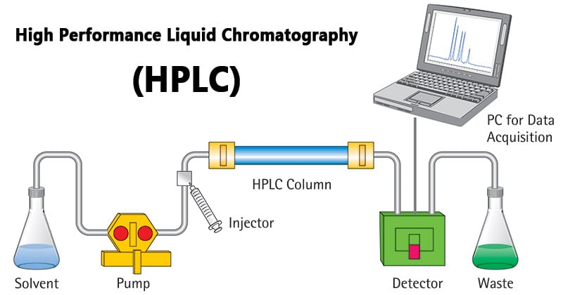
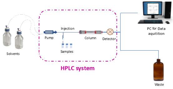
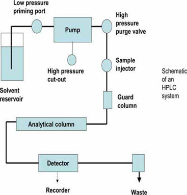
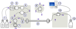
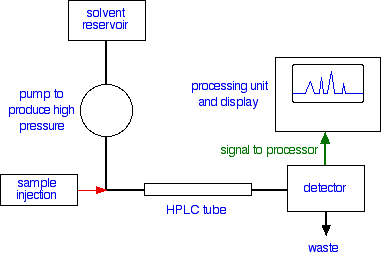
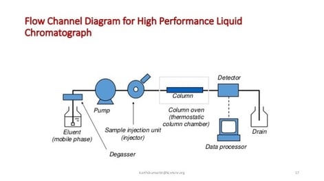
Figure 1 Block diagram of an HPLC system A reservoir holds the solvent (also called the “mobile phase” because it moves) A highpressure pump generates a specified flow rate of mobile phase The injector introduces (injects) the sample into the continuously flowing mobile phase stream that carries the sample into the HPLC column The column is the heart of HPLC, since it contains the chromatographic packing material (stationary phase) needed for the separation to take place. The extensive portfolio of innovative Thermo Scientific HPLC and UHPLC systems, empowers you to choose the system that best fits your requirements Visit the table below to get an overview of our portfolio and browse highlights of our analytical HPLC and UHPLC systems, applicationspecific HPLC and UHPLC systems and nano, capillary, and micro. The detector measures the concentration of sample bands as they leave the column and pass through the detector flow cell When no band is passing through the detector, a constant signal is recorded called the Baseline of the chromatogram or detector When a sample band reaches the detector, the detector responds to the difference in the mobile phase properties caused by the presence of the.
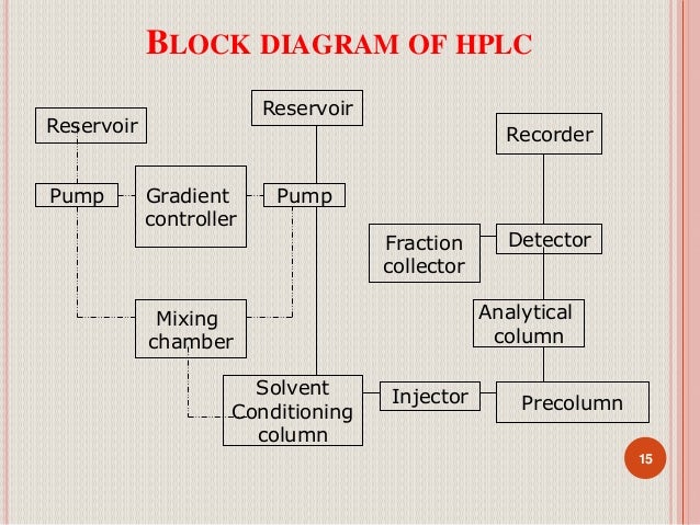
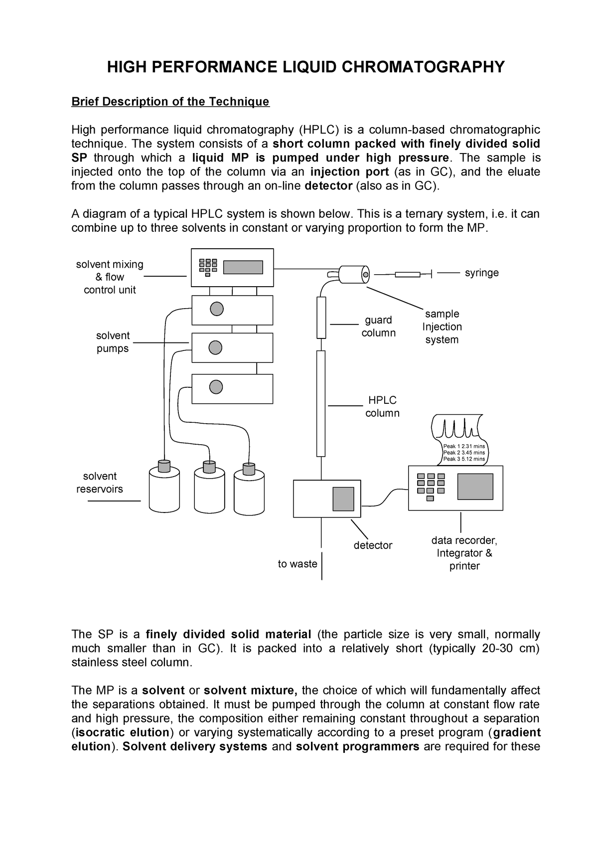
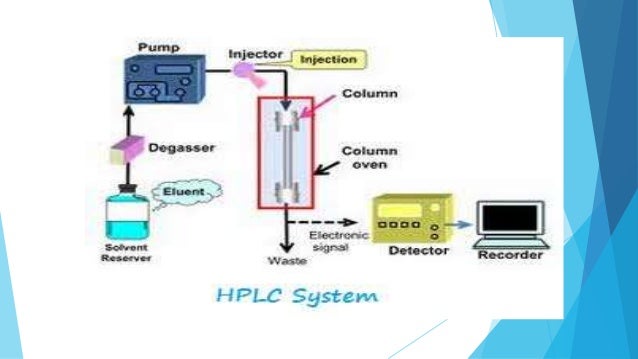
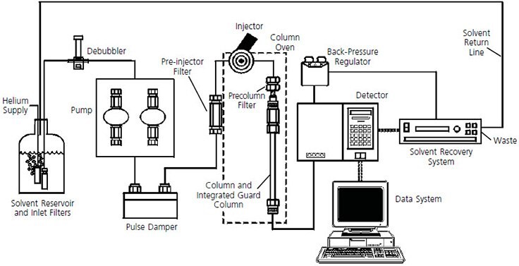
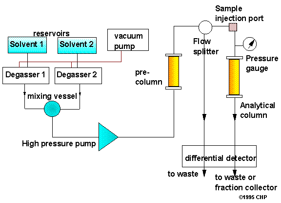
Figure 1 A flow diagram of an HPLC system Depending on the overall requirements and nature of the sample and analytes, some of these steps will not be necessary during HPLC analysis For example, a satisfactory separation may be found during step 2, thus steps 3 and 4 may not be required. 10 General information about your system System Configuration System Configuration Manual isocratic HPLC System G1380AA standard configuration • G1310A isocratic pump with solvent cabinet • G1328A manual injector (MI) • G1314A variable wavelength detector (VWD) with standard flow cell (10 mm path. INSTRUMENTATION OF HPLC Solvent storage bottle Gradient controller and mixing unit Degassing of solvents Pump Pressure gauge Precolumn Sample introduction system Column Detector Recorder 28 29 FLOW DIAGRAM OF HPLC instrument 29 30.
Note It is important to read the introductory page about thin layer chromatography before you continue with this one particularly the part about how thin layer chromatography works High performance liquid chromatography works on the same basic principle HPLC is essentially an adaptation of column chromatography so it might be a good idea to have a (very quick) look at that as well. Many issues in the LC system appear as chenges in the chromatogram Some of these can be solved by changes in the instrument, however, other problems require modification of the assay procedure Setting the proper column type, precolumn or guard column, tubings, detector cell and mobile phase are keys to good chromatography. Typically the wavelength range used in UV detection for HPLC is in the range 0 – 400nm, which covers both UV and the lower part of the visible spectrum Figure 1 shows the electromagnetic spectrum and the relationship between the wavelength of light and frequency.
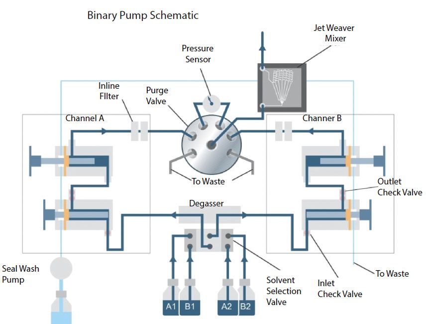
Modular HPLC System – basic configuration with isocratic pump, manual injector, variable wavelength detector, and handheld controller Modular HPLC System – highend configuration with quaternary pump, autosampler, column thermostat, diode array detector, and computer with control and data analysis SW Integrated HPLC System. Waters 2690 Separations Module Operator’s Guide 34 Maple Street Milford, MA WATTP, Revision 2. Bubble formation on mixing of solvents can lead to a number of problems in HPLC analysis which can be prevented by degassing of mobile phase Unstable and noisy baselines Lower flow rate precision of pump due to cavitations in piston chamber or effect on check valve performance.
Myosmine were prepared and quantified using high performance liquid chromatography (HPLC) Various elution schemes were tested and adjusted for optimal analyte resolution, and a final elution scheme was developed to characterize ecigarette alkaloids. Isolating HPLC Problems In an HPLC system, problems can arise from many sources First define the problem, then isolate the source Use Table 1 to determine which component(s) may be causing the trouble A process of elimination will usually enable you to pinpoint the specific cause and correct the problem. The video shows an automated HPLC system that loads the sample on its own and gives you final results on the monitor The more automation, the less is the time consumed and also the chances for errors HPLC Injector This is the part of HPLC used to load the sample into the column In older and manually operated instruments, there are two.
As shown in the schematic diagram in Figure above, HPLC instrumentation includes a pump, injector, column, detector and integrator or acquisition and display system The heart of the system is the column where separation occurs 1. HPLC instrument has an injection system, a pump, column, detectors and a recorder HPLC Analysis Principle The principle involved in HPLC testing is the separation of compounds in a mixture more efficiently and also quickly than that of traditional column chromatography. HPLC Operation A simple way to understand how we achieve the separation of the compounds contained in a sample is to view the diagram in Figure G Mobile phase enters the column from the left, passes through the particle bed, and exits at the right Flow direction is represented by green arrows.
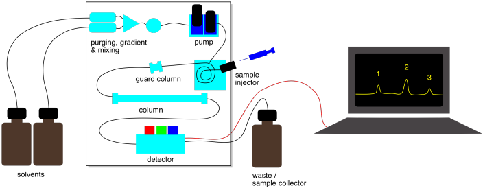
From the diagram above it is shown that the mobile phase is brought to the pump where it is sent to the column under a specific pressure The sample is injected into the system before the column and is injected into the mobile phase stream. The detector measures the concentration of sample bands as they leave the column and pass through the detector flow cell When no band is passing through the detector, a constant signal is recorded called the Baseline of the chromatogram or detector When a sample band reaches the detector, the detector responds to the difference in the mobile phase properties caused by the presence of the. The only purpose for this part of the system is to protect the analytical column from contamination, removes any potentially high absorbing compounds It can be discarded and replaced if contaminated Replacing this also decreases the pressure in the system.
Bleshooting your HPLC system This guide is organized by five major categories of symptoms to help you quickly identify the source of the problem(s) you are encountering • pressure abnormalities • leaks • problems with the chromatogram • injector problems • other problems detected by the senses of smell, sight, and sound. Modern high performance liquid chromatography or HPLC has its roots in this separation, the first form of liquid chromatography (B\) is a constant that describes the longitudinal diffusion that occurs in the system \(C\) is a constant that describes the rate of adsorption and desorption of the analyte to the stationary phase \(A\), \(B. Figure 1250 shows a block diagram of a typical HPLC–MS instrument The effluent from the column enters the mass spectrometer’s ion source using an interface the removes most of the mobile phase, an essential need because of the incompatibility between the liquid mobile phase and the mass spectrometer’s high vacuum environment.
Belov et al were able to detect proteins at the zeptomole (10 −21 moles) level using a 15 µm ID column of 80 cm lengthHere, the flow rates needed for operating such small ID columns decrease exponentially with column diameter If, for example, a 1 mm ID HPLC column needed a flow rate of 50 µl/min, a column of 75 µm ID would need approximately 300 nl/min. 601d Block Diagram of HPLC System 6016 1/94 601e Column Outlet Fittings 6017 1/94 601f Low Dead Volume Fitting 6017 1/94 601g Standard Internal Fitting 6018 1/94. Figure 1 A flow diagram of an HPLC system Depending on the overall requirements and nature of the sample and analytes, some of these steps will not be necessary during HPLC analysis For example, a satisfactory separation may be found during step 2, thus steps 3 and 4 may not be required.
Modular HPLC System – basic configuration with isocratic pump, manual injector, variable wavelength detector, and handheld controller Modular HPLC System – highend configuration with quaternary pump, autosampler, column thermostat, diode array detector, and computer with control and data analysis SW Integrated HPLC System. Temperature, injection sequence, etc) and acquires data from the detector. Isolating HPLC Problems In an HPLC system, problems can arise from many sources First define the problem, then isolate the source Use Table 1 to determine which component(s) may be causing the trouble A process of elimination will usually enable you to pinpoint the specific cause and correct the problem.
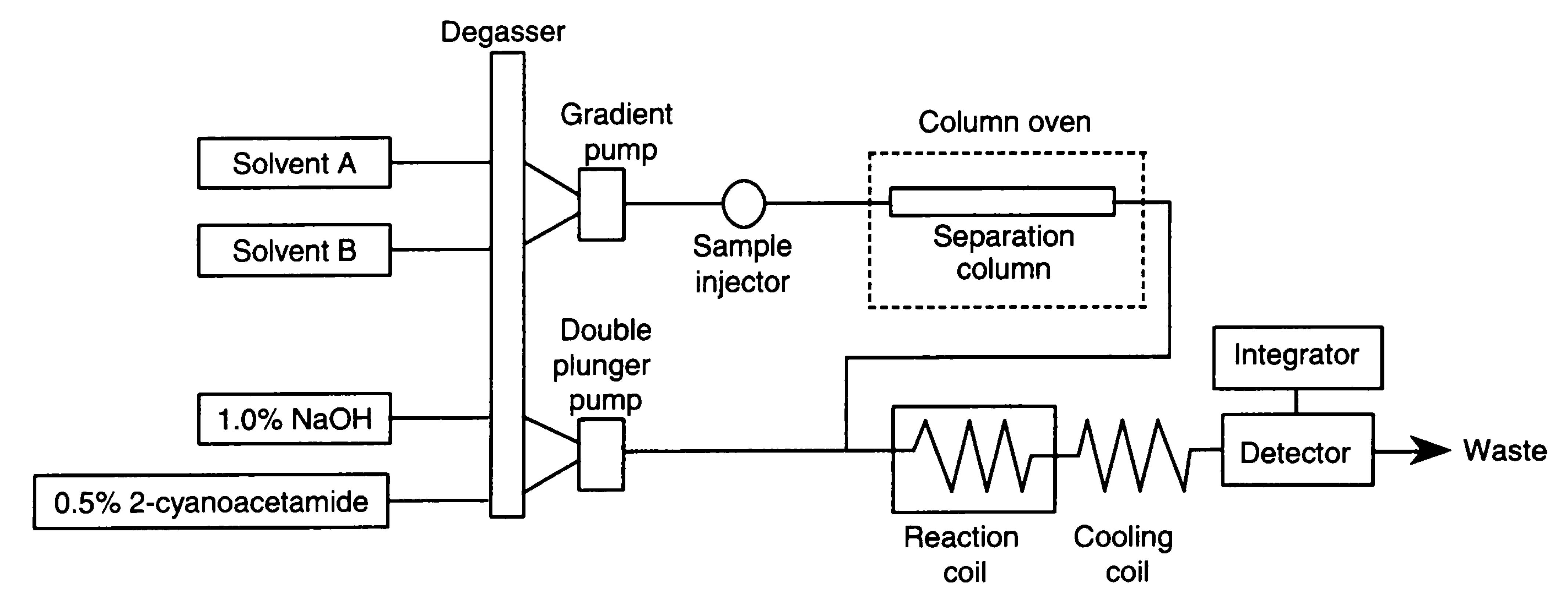
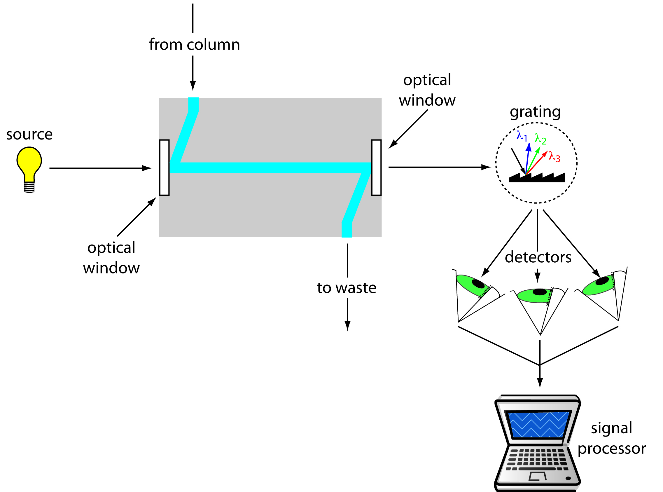
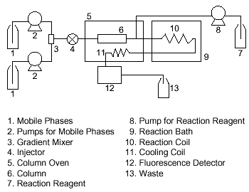
Figure 307 represents the schematic diagram of a doublebeam UV detector used in HPLC system Initially, dualwavelength instruments having 254 and/or 280 nm were introduced which is presently being replaced by more sophisticated and updated variable wavelength detectors spread over wide range between nm capable of performing more. Operating an HPLC system with a postcolumn derivatization system can be as routine as regular LC The benefits from this LC/postcolumn combination include minimal sample pretreatment, greatly improved sensitivity, and enhanced selectivity for compounds that would normally be much more difficult to detect. PerkinElmer Series 0 HPLC Operating Procedure 12/2/11 RC Equipment Overview This document outlines the basic procedure for the Sedex light using scattering detector and the PE series 0 HPLC system to detect sugars To use this system to detect and analyze other compounds consult the lab manager.
Figure 1 Block Diagram of an HPLC Your desired solvent mixture travels through capillary tubes, from the solvent reservoir to the pump, where it is becomes highly pressurized The pump is also used to control the flow rate of the mobile phase substance,which is typically measured in mL/minute. Presented in Figure 5 is a schematic diagram showing a typical layout of a HPLC/UHPLC system Testing of static mixers was performed by locating the mixer immediately downstream of the pump and upstream of the sample injector and separation column. Schematic diagram and basic components of HPLC system• Most of the HPLC systems are modular One can just add a new component or accessory to change or extend the capabilities 2 Schematic diagram of HPLC system 3 Mobile phase reservoir and its Functions• Is a tray having glass bottles fitted a lid and 1/8 inch diameter PTFE tubing to.
Highperformance liquid chromatography (HPLC), formerly referred to as highpressure liquid chromatography, is a technique in analytical chemistry used to separate, identify, and quantify each component in a mixture It relies on pumps to pass a pressurized liquid solvent containing the sample mixture through a column filled with a solid adsorbent material. PerkinElmer Series 0 HPLC Operating Procedure 12/2/11 RC Equipment Overview This document outlines the basic procedure for the Sedex light using scattering detector and the PE series 0 HPLC system to detect sugars To use this system to detect and analyze other compounds consult the lab manager. HPLC adalah singkatan dari High Performance Liquid Chromatography, atau dikenal juga dengan istilah KCKT(Kromatografi Cair Kinerja Tinggi) Pada artikel kali ini penulis akan membahas tentang alat HPLC yang biasa ada di laboratorium, pembahasannya akan cukup panjang ya Mulai dari pengertian hplc, fungsi hplc, demo unit hplc, prinsip kerja hplc, jenis jenis hplc, bagian bagian hplc, cara.
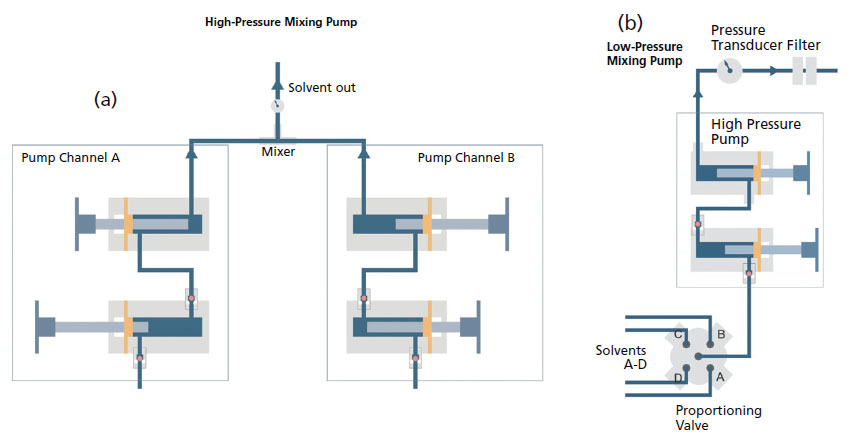
In highperformance liquid chromatography (HPLC) we inject the sample, which is in solution form, into a liquid mobile phase The mobile phase carries the sample through a packed or capillary column that separates the sample’s components based on their ability to partition between the mobile phase and the stationary phase. The role of the pump is to propel (force) a liquid (the mobile phase) through the chromatograph at a specific flow rate, expressed in ml/min Normal flow rates in HPLC are 12 ml/min and typical pumps can reach pressures in the range of 00 – 9000 psi but in applications covered under UHPLC mode operating pressure can be as high as psi. Figure 1250 shows a block diagram of a typical HPLC–MS instrument The effluent from the column enters the mass spectrometer’s ion source using an interface the removes most of the mobile phase, an essential need because of the incompatibility between the liquid mobile phase and the mass spectrometer’s high vacuum environment.
601d Block Diagram of HPLC System 6016 1/94 601e Column Outlet Fittings 6017 1/94 601f Low Dead Volume Fitting 6017 1/94 601g Standard Internal Fitting 6018 1/94. Agilent 1100 Series HPLC System is available from The Lab World Group For more information, please visit us at https//wwwthelabworldgroupcom/agilent110. Typically the wavelength range used in UV detection for HPLC is in the range 0 – 400nm, which covers both UV and the lower part of the visible spectrum Figure 1 shows the electromagnetic spectrum and the relationship between the wavelength of light and frequency.
The Agilent 10 Series HPLC System was introduced in 10, with a modular design allowing users to define a configuration ideally suited to meet their HPLC and UHPLC applications and requirements In 1995, then company Hewlet Packard introduced the 1100 Series liquid chromatograph, which was designed to help chemists support faster productdevelopment cycles (such as those for new. The key difference between reverse phase and normal phase HPLC is that the reverse phase HPLC uses a nonpolar stationary phase and a polar mobile phase whereas the normal phase HPLC uses a polar stationary phase and a less polar mobile phase The normal phase HPLC is the oldest technique of HPLC that Tswett used in his separations of plant extracts;.

Hplc Pump Jasco Inc Bioz Ratings For Life Science Research

Hplc

Figure 1 From Speciation Of Arsenic W And Arsenic V In Sediment Extracts By High Performance Liquid Chromatography Hydride Generation Atomic Absorption Spectrophotometry Semantic Scholar

Hplc Calibration Procedure Pharmaceutical Guidelines

Block Diagram Of The Hplc System With In Line Postcolumn Oxidation And Download Scientific Diagram

Hplc

Block Diagram Of The Hplc System With In Line Postcolumn Oxidation And Download Scientific Diagram

Parts Of High Performance Liquid Chromatography Hplc

Basic Concepts Fundamentals Working Principles And Applications Of Analytical Instruments Hplc

How Does High Performance Liquid Chromatography Work Waters
Hplc Analysis Of Glycosaminoglycans Glycoscience Protocol Online Database
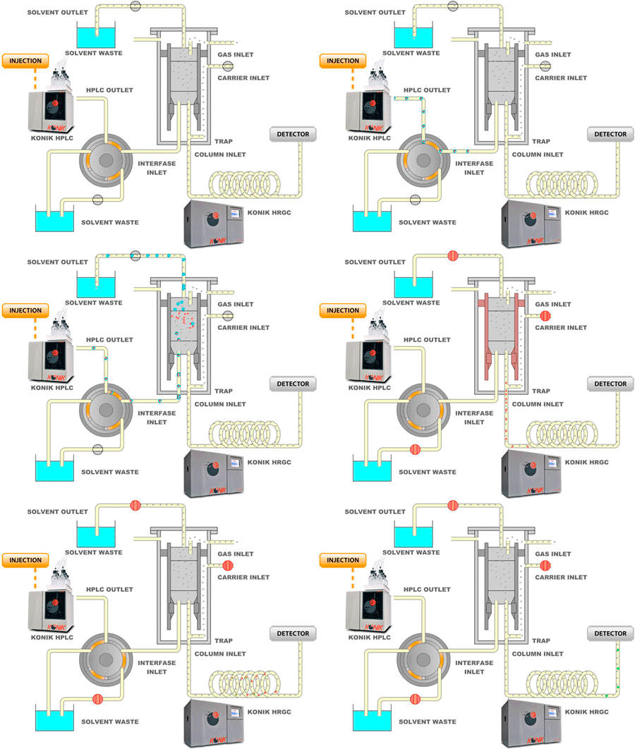
Hplc Gc

Figure 1 From High Performance Liquid Chromatography For Hormone Assay Semantic Scholar

Factors Affecting Resolution In Hplc Sigma Aldrich

Schematic Layout Of A Hplc System Download Scientific Diagram

Building Your Hplc

Instrumentation High Performance Liquid Chromatography Hplc
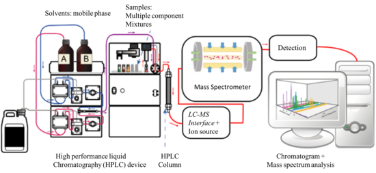
Liquid Chromatography Mass Spectrometry Wikipedia

Principle Of Hplc Liquid Chromatography Pharmaceutical Guidelines

High Performance Liquid Chromatography An Overview Sciencedirect Topics

Schematic Diagram Of An Hplc Ecd System Setup Black Lines Indicate The Download Scientific Diagram
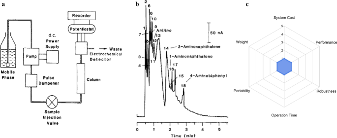
A Review Of Portable High Performance Liquid Chromatography The Future Of The Field Springerlink
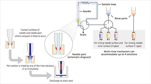
Minimizing Hplc Carryover Lab Manager

Hplc System Components Galak Chromatography Technology

Schematic Diagram Of A Semiautomated Two Dimensional Hplc System To Download Scientific Diagram

Water For Hplc Application Water Purification Merck

Hplc High Perfermance Liquid Chromatography For Beginners Simple Animation Hd Youtube

High Performance Liquid Chromatography

Hplc Instrumentation 19 Autosampler Sampling Valve Youtube

Sample Injection Liquid Chromatography Hplc Injection Methods Knauer
Chromatography
12 5 High Performance Liquid Chromatography Chemistry Libretexts
High Performance Liquid Chromatography Full Notes Studocu

High Performance Liquid Chromatography
Q Tbn And9gcttguyh3vq5hwfoe S3s Xrymr47f05j Qldcv8adohtuhtk Ah Usqp Cau

Gc Chromatogram
High Performance Liquid Chromatography Hplc Creative Biolabs

Hplc High Performance Liquid Chromatography Chromatography

Mixing And Mixers In Liquid Chromatography Why When And How Much Part I The Pump Chromatography Online

How Does High Performance Liquid Chromatography Work Waters
Modern Hplc Pumps Perspectives Principles And Practices Chromatography Online

Schematic Diagram Of An Hplc System Download Scientific Diagram

Reducing Hplc And Uhplc System Noise And Volume With High Performance Static Mixers Chromatography Online
Modern Hplc Pumps Perspectives Principles And Practices Chromatography Online
Q Tbn And9gcsm1xbdrlst2sujsvoq Nvged1xtjkk6lvf4lbca5e7hq3zejrh Usqp Cau
Www Agilent Com Cs Library Usermanuals Public G1380 Pdf

Hplc System Components Liquid Chromatography Shimadzu Prominence
Instrumentation Of Hplc

The Manifold Diagram Of Online Spe Hplc System Sp Syringe Pump Sl Download Scientific Diagram
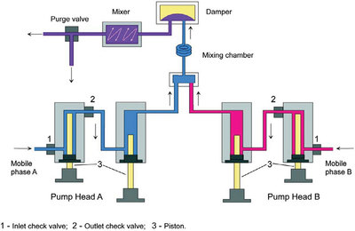
A Novel Performance Test For Outlet Check Valve Function In Hplc Pumps American Laboratory
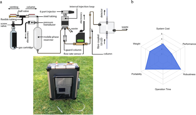
A Review Of Portable High Performance Liquid Chromatography The Future Of The Field Springerlink
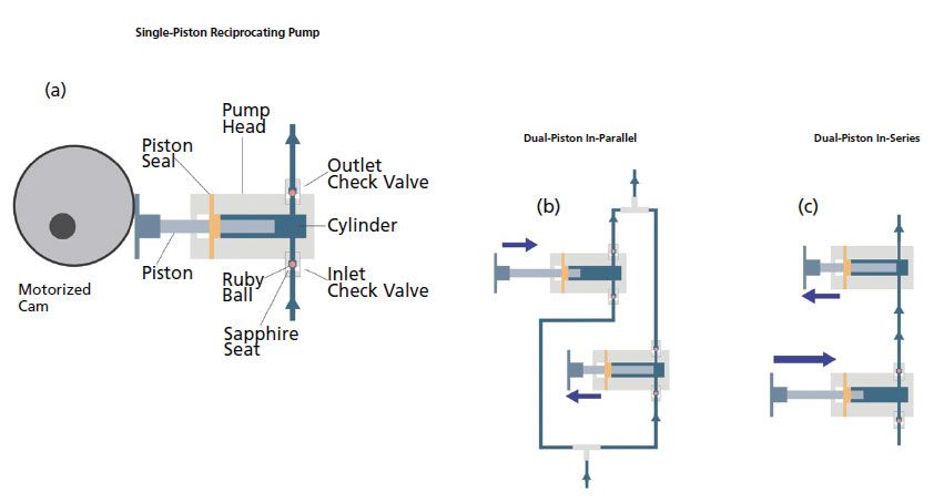
Modern Hplc Pumps Perspectives Principles And Practices Chromatography Online
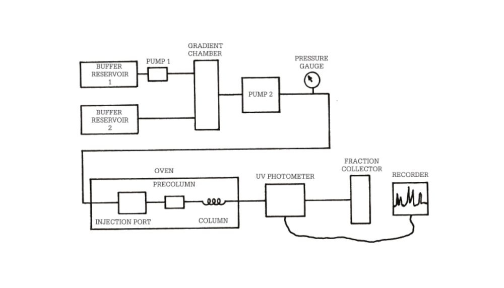
The Top 10 Breakthroughs In Hplc History
High Performance Liquid Chromatography Hplc Instrumentation Microbe Notes
High Performance Liquid Chromatography

Hplc Pain Points Part 1 Cytiva Formerly Ge Healthcare Life Sciences

How Does High Performance Liquid Chromatography Work Waters

Schematic Diagram Of The High Performance Liquid Chromatography Hplc Download Scientific Diagram

Schematic Diagram Of A Typical Hplc Or Hpic Set Up With A Simple Download Scientific Diagram

Analsci Hplc Tour Introduction

Applications Of High Performance Liquid Chromatography In The Analysis Of Herbal Products Sciencedirect

High Performance Liquid Chromatography Hplc Basics
Detection Methods 2 Shimadzu Shimadzu Corporation

Basic Principles Of Hplc Ms Lc Ms Chemyx Inc

Kutztown University Hplc Resources Kutztown University

Advantages And Disadvantages Of Different Hplc Pump Configurations
High Performance Liquid Chromatography Hplc

Block Diagram Of Hplc System Radio Wiring Diagram

Hplc Help Center

Schematic Diagram Of The High Performance Liquid Chromatography Hplc Download Scientific Diagram
Q Tbn And9gct2ow8nr5e6qtrfxebsotlj3b K1e0ozzwekkn5wryb Sx5ix Usqp Cau

3 Principle And System Configuration Of Hplc 3 Hitachi High Tech Global

High Performance Liquid Chromatography Hplc System With Reaction Download Scientific Diagram
High Performance Liquid Chromatography For Hormone Assay Springerlink

Pteridine Determination In Human Serum With Special Emphasis On Hplc Methods With Fluorimetric Detection In Pteridines Volume 28 Issue 2 17
Principles Of Hplc 2 Hplc System Configuration Jasco Global

Hplc Man

Pradeep Research Group

Instrumentation High Performance Liquid Chromatography Hplc

1 Principle And System Configuration Of Hplc 1 Hitachi High Tech Global
High Performance Liquid Chromatography Wikipedia
Hplc Troubleshooting Guide Sigma Aldrich

Minimizing Hplc Carryover Lab Manager

Schematic Diagram Of A Typical Hplc Or Hpic Set Up With A Simple Download Scientific Diagram

Schematic Diagram Of A Typical Hplc Or Hpic Set Up With A Binary Download Scientific Diagram

Schematic Diagram Of An Hplc System Download Scientific Diagram

3 2 High Performance Liquid Chromatography Chemistry Libretexts

Column Switching System Diagram

Lab Manual Pdf Version Experiment 1 Experiment 2 Experiment 3 Experiment 4 Experiment 5 Experiment 6 Experiment 7 Experiment 8 Schedule Program Schedule Seminars Homework Pictures All Albums Celebrity Group Photos Seminars Farewells Ice
Definition Of High Performance Liquid Chromatography Hplc Chemistry Dictionary

Hplc Principles And Parameters Knauer

The Hplc System Simply Explained

General Instrumentation In Hplc Sciencedirect

Schematic Diagram Of A Typical Hplc Instrument Setup Download Scientific Diagram
High Performance Liquid Chromatography Hplc
Tips For Hplc Column Care And Sampling System Maintenance

Hplc Instruments Youtube


